Table of Contents
Advertisement
Quick Links
OPERATION, SERVICE AND
MAINTENANCE INSTRUCTION
Direct Gas-Fired Heater Modules
ANSI Z83.25 (2017) – CSA 3.19 (2017)
Direct gas-fired process air heaters
WARNING:
!
FIRE OR EXPLOSION HAZARD
Failure to follow safety warnings exactly could result in serious injury,
death or property damage.
Be sure to read and understand the installation, operation and service
instructions in this manual.
Improper installation, adjustment, alteration, service or maintenance can
cause serious injury, death or property damage.
Do not store or use gasoline or other flammable vapors and liquids in the
vicinity of this or any other appliance.
WHAT TO DO IF YOU SMELL GAS
·
Do not try to light any appliance
·
Do not touch any electrical switch; do not use any phone in your building
·
Leave the building immediately
·
Immediately call your gas supplier from a phone remote from the
building. Follow the gas supplier's instructions.
·
If you cannot reach your gas supplier, call the fire department.
Installation must be performed by a qualified installer, service agency or gas
supplier
.
This manual must be kept with the appliance for future reference.
Manufactured by:
Heatco Inc
50 Heatco Court
Cartersville, Ga. 30120
DF Series
1
DF-USM-MAN-LIST-Z83.25-1
Advertisement
Table of Contents

Related Manuals for heatco DF Series


Summary of Contents for heatco DF Series
- Page 1 OPERATION, SERVICE AND MAINTENANCE INSTRUCTION DF Series Direct Gas-Fired Heater Modules ANSI Z83.25 (2017) – CSA 3.19 (2017) Direct gas-fired process air heaters WARNING: FIRE OR EXPLOSION HAZARD Failure to follow safety warnings exactly could result in serious injury, death or property damage.
-
Page 2: Table Of Contents
The information provided in this manual applies to the furnace module installed as part of a manufactured package system and to its operation, maintenance, and service. Refer to the system manufacturer’s instructions for information related to all other components. Table of Contents Installation Requirements. -
Page 3: Installation Requirements
Installation Requirements All heater installations must be in accordance with the National Fuel Gas Code ANSI Z223.1 (NFPA 54) in the United States and Can/CGA-B149 Installation Code in Canada, and all other applicable local codes and ordinances. These requirements include but are not limited to: ·... -
Page 4: Direct-Fired Heat Module Application
Filters are required upstream of the direct gas-fired burner assembly. Particulate removal filters are not provided by Heatco and must be approved by the authority having jurisdiction. Minimum distance between the burner and blower should ensure proper stratification of the combustion air. -
Page 5: Paint Booth Application
IV. Paint Booth Application In a paint booth application, an interlock shall be installed in the field to lock out the paint spraying equipment unless the process heater is operated in the ventilation air mode. The customer safety interlock should be wired in series with the heat enable signal. See supplied wiring diagram. An interlock shall be installed in the field so that when the heater is operated in the ventilation air mode for an minimum of three (3) minutes at the start of the bake or drying cycle with the paint spraying equipment locked out. -
Page 6: Circulating Air Supply
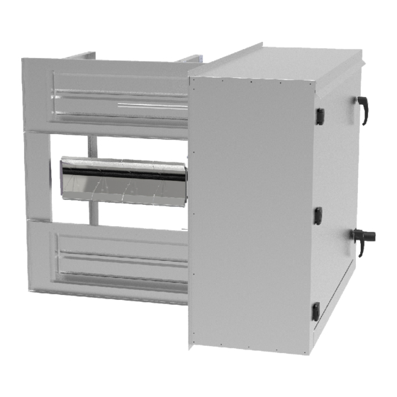
VII. Circulating Air Supply DF Series Direct gas-fired heater modules should ALWAYS be installed with burners in parallel with the circulating airflow direction. The circulating air is to be uniform across the full length of profile plate opening. The direct gas-fired module is designed to operate with all circulating air passing over the burners. - Page 7 drop will be close to 0.25” w.c. These operating parameters are within the combustion air switch high and low limits (0.2” w.c. to 1.2” w.c.). Figure 6 – Variable Profile Plate Damper Construction Profile Modulating Dampers Figure 7 – Component Locations (Typical)
-
Page 8: Gas Supply, Piping And Connections
X. Gas Supply, Piping and Connections 1. Installation and sizing of piping must conform with local building codes and ordinances, or with ANSI Z223.1 the National Fuel Gas Code. In Canada, installation must be in accordance with CAN/CGA –B149.1 Installation Codes. -
Page 9: Direct Gas-Fired Heat Module Controls
XII. Operation and Adjustment SEE Heatco website for information and start-up procedure videos. Most direct gas-fired heater module modules come with a pilot. If the module is < 400 MBH it is equipped with a direct spark ignition device that automatically lights the gas burner. DO NOT try to light burners by hand. - Page 10 Start-up A pressure tap is used to measure the differential at the burner and to set high fire gas pressure (See Manifold Pressure Adjustment on Page 17-18). The manifold pressure tap is 1/8” and located between modulating valve and the burner(s). Close the inlet manual shut off valve and open the manual shut off located between the modulating valve and the burner.
- Page 11 RA / RR: If using a remote Temperature selector, remove the leads off of Terminals 4 & 5 on the Maxitrol A1044R. (See Figure 10C) Place the supplied 12,000 Ohm resistor across Terminals 4 & 5. Rotate the on board temperature selector dial fully CW to run unit at full input high fire.
- Page 12 Figure 10C– A1044R Figure 11– MR 212 Modulating Regulator Valve Figure 12 – M 411, 511, 611 Modulating Valve...
-
Page 13: Burner Trouble Shooting
Figure 13 – Robertshaw Regulator / Pilot Gas Valve Figure 14 – Honeywell Regulator Valve XIII. Burner Trouble Shooting The Burner is only a component of the complete system. For trouble shooting of the equipment, contact the OEM (Original Equipment Manufacturer) or the component manufacturer. If the pilot fails to light: install a manometer on the pilot pressure tap. -
Page 14: Manifold Pressure Adjustment
XIV. Manifold Pressure Adjustment The correct input capacity of the direct gas-fired heater module is controlled by the burner gas differential manifold pressure. A pressure tap is provided in each heat module gas train manifold. Manifold pressure must be checked at start-up and during any service or maintenance. -
Page 15: Electrical Controls & Wiring
Figure 17 – Flame Appearance High Fire (550 MBH/ ft of burner) Low Fire (20 MBH/ ft of burner) XV. Electrical Controls & Wiring All electrical wiring must be done in accordance with the National Electric Code, ANSI/NFPA No. 70. Operating electrical controls are mounted within the heat module vestibule or on the vestibule panel. -
Page 16: Burner Maintenance
XVI. Burner Maintenance Annual maintenance of the burner is recommended to ensure trouble free operation. Clean the burner plates Clear the burner gas and air ports Change the spark rod igniter Insure the flame sensor is in good condition Use a stiff wire brush to clean the burner plates. Scrub both sides of the stainless-steel burner plates to remove any soot or other crud, which may be on the burner. -
Page 17: Filter Maintenance
Filters are required upstream of the direct gas-fired burner assembly. Particulate removal filters are not provided by Heatco and must be approved by the authority having jurisdiction. Filters must be installed in the return air duct system and have the means to facilitate inspection, maintenance, cleaning, and access to fire protection devices.
Need help?
Do you have a question about the DF Series and is the answer not in the manual?
Questions and answers