
Related Manuals for Adexa AP238- PS15- 36


Summary of Contents for Adexa AP238- PS15- 36
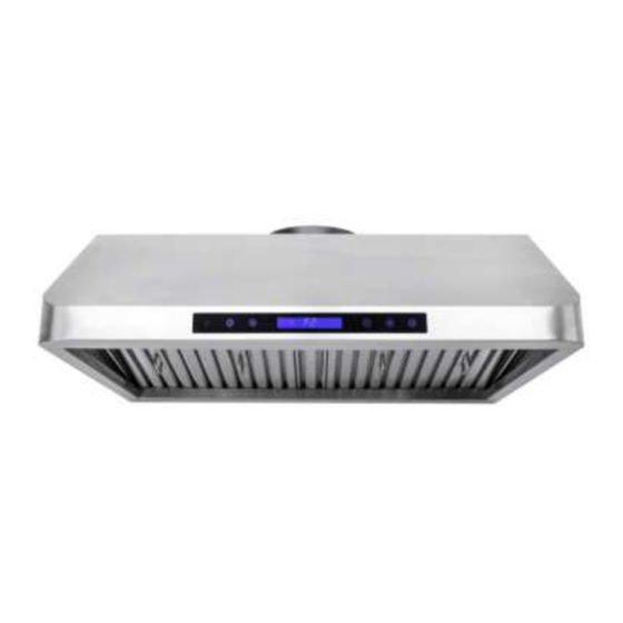
- Page 1 UNDER-MOUNT HOOD MODEL : AP 238- PS15- 36 INSTALLATION GUIDE / USE AND CARE MANUAL IMPORTANT: Read and save these instructions. Installer: Leave this manual with the homeowner. Homeowner: Keep this guide for future reference. 2021A...
-
Page 3: Table Of Contents
Table of Contents IMPORTANT SAFETY PRECAUTIONS ..............4- 5 INSTALLATION INSTRUCTIONS ................6-13 OPERATING THE HOOD ..................14- 16 MAINTENANCE......................17-18 WARRANTY......................... 19 APPROVED FOR APPLIANCES OF RESIDENTIAL USE ONLY. READ AND SAVE THESE INSTRUCTIONS. PLEASE READ THE ENTIRE INSTRUCTIONS BEFORE YOU BEGIN. -
Page 4: Important Safety Precautions
IMPORTANT SAFETY PRECAUTIONS READ AND SAVE THESE INSTRUCTIONS CAUTION: For residential use only. Do not use to exhaust hazardous or explosive materials and/or vapors. CAUTION: Range hood may have very sharp edges; please wear protective gloves when installing, cleaning or servicing the unit. - Page 5 WARNING TO REDUCE THE RISK OF FIRE, USE ONLY METAL DUCTWORK. WARNING TO REDUCE THE RISK OF A RANGE TOP GREASE FIRE: Never leave a range unattended. Boil-overs cause smoke and greasy spillovers that may ignite. Heat oils slowly on low or medium setting. Always turn hood ON when cooking at high heat.
-
Page 6: Installation Instructions
INSTALLATION INSTRUCTIONS TOOLS NEEDED TO INSTALL THE RANGE HOOD Needle nose pliers Safety gloves and goggles Scissors (to cut duct tape) Electrical drill Duct tape Phillips screwdriver Marker or pencil Flathead screwdriver Level Hammer ... - Page 7 DIMENSIONS FOR 30’’ HOOD Overall Rear Knockout Holes Installation Floor to ceiling height variable Floor to counter top height 36" (standard) Recommended height between cooking surface and bottom of the 28"-30" hood Hood height 9.8" Cabinet height The information contained herein is based on sources that we believe to be reliable, but is not guaranteed by us, may be incomplete and/or may change without notice...
- Page 8 BEFORE INSTALLING THE HOOD For the most efficient airflow exhaust, use a straight run or as few elbows as possible. Vent unit to the exterior only. At least two people are required for installation. Remove the range hood from the carton packaging and place on a flat surface for assembly. ...
- Page 9 Venting Requirements Height & Clearance • Vent system must evacuate to the exterior (through the roof or side wall). • DO NOT terminate the vent system in an attic or other enclosed area. • Use rigid metal/aluminum ventonly. • NEVER use plastic vent or plastic vent cover. Cabinet Cabinet •...
- Page 10 IMPORTANT • A minimum of 8” round (standard for this range hood) must be used to maintain maximum airflow efficiency. • Always use rigid type metal/aluminum ducts if available to maximize airflow when connecting to duct provided. VENTING METHODS INSTALLATION DIAGRAMS •...
- Page 11 ELECTRICAL REQUIREMENTS AND INSTALLATION WARNING THIS RANGE HOOD MUST BE PROPERLY GROUNDED. TURN OFF ELECTRICAL POWER AT SERVICE ENTRANCE BEFORE WIRING. CHECK TO MAKE SURE THAT THE ELECTRIC CORD IS NOT IN CONTACT WITH THE SHARP EDGES OF THE APPLIANCE. IMPROPER GROUNDING CAN RESULT IN A RISK OF ELECTRIC SHOCK.
- Page 12 INSTALLATION Measure the distance between the cooking surface and the bottom of the range hood. A distance of 27” to 30” is recommended*. Due to different ceiling height configurations, the recommended height may not be applicable Step 1: You have two options for installing this range hood (see INSTALLATION DIAGRAMS on page 7): A.
- Page 13 INSTALLATION (continued) Step 2: For safety purpose, pre-drilled mounting holes are provided through the back of the hood. For a more secure installation, use as many mounting holes as needed to secure from the inside of hood. Use an 8” round metal pipe (follow building codes in your area) to connect the exhaust on the hood to the ductwork above, as illustrated in figure 4.
-
Page 14: Operating The Hood
RANGE HOOD OPERATIONS Control Panel Layout and Buttons Configurations: In addition to the remote-control feature, this range hood is also equipped with a heat sensor that will self- calibrate in 5 seconds when the range hood is first electrically activated and beeps when self-calibration is done. - Page 15 CIRCUIT DIAGRAM SPECIFICATIONS Specificat ions Body Design Seamless St ainless St eel, Sat in Finish 220-240V/ 50Hz Pow er Rat ing General Input Pow er 246W M ot or Input Pow er 240W(120W+120W) Ampere Levels Of Speed Cont rol 4 Leves 900CFM Airflow (M ax) 1.5Sone(46dB) / 3.5Sone(58dB) / 5.3Sone(64dB) / 7.5Sone(69dB)
- Page 16 RANGE HOOD ASSEM BLY Descript ion Quant it y Hood-M ount ing Bracket Hood Body Light Cont rol Panel Oil Tunnel Blow er Assembly (M ot or, Fan Blade, Prot ect ive Grill and Squirrel Cage) Elect rical Assembly St ainless St eel Spacer Baffle Filt er Pow er Cord BLOWER ASSEM BLY...
-
Page 17: Maintenance
MAINTENANCE SAFETY WARNING: NEVER PUT YOUR HAND INTO AREA HOUSING THE FAN For optimal operation, clean range hood, surfaces and filters regularly. Regular care will help preserve the appearance of the range hood. CLEANING THE EXTERIOR SURFACES Clean periodically with hot soapy water and clean cotton cloth. Do not use corrosive or abrasive detergent or steel wool pads, which will scratch and damage the stainless-steel surface. - Page 18 REPLACING THE LED LIGHT BULBS CAUTION: LED lamps can only be replaced with a new LED lamp. The lamp rating must be equal to the one already used. Make sure all the control switches are off and the hood is unplugged, or the breaker is OFF. Replacing the LED light fixture: •...
-
Page 19: Warranty
SERVICE AND WARRANTY LIMITED WARRANTY One Year Part s Warrant y: For one year from t he dat e of original purchase, your local reseller w ill provide free of charge, non-consumable replacement part s or component s t hat failed due t o manufact uring defect s. Subject t o t he condit ions and limit at ions set fort h below , your local reseller w ill, at it s opt ion, eit her repair or replace any part of it s product s t hat prove defect ive by reason of improper w orkmanship or mat erials.