Table of Contents
Advertisement
Quick Links
Table of Content 43051081
..................................................................................................................................
.........................................................................................................................................
..............................................................................................................................
.......................................................................................................................................
..................................................................................................................................
Version No. 1-7 - 01.08.2022
.........................................................................................................................
......................................................................................................................
.....................................................................................................................
......................................................................................................................
.....................................................................................................................
...................................................................................................................
............................................................................................................
...............................................................................................................
........................................................................................................................
.............................................................................................................
.....................................................................................................................
.........................................................................................................
................................................................................................................
..........................................................................
Doc. No. 9943051081
2
3
4
5
6
7
8
9
10
11
12
13
14
15
16
16
16
17
18
1 / 19
Advertisement
Table of Contents

Related Manuals for Seifert KG 4305


Summary of Contents for Seifert KG 4305
-
Page 1: Table Of Contents
Table of Content 43051081 1. User manual ..........................2. Legal regulations ......................... 3. Safety instructions ........................4. Settings ............................5. Functional principle ........................6. Technical data ..........................7. Performance graph ........................8. Mounting ............................9. Mounting Principle ........................10. Cut Out Dimension ........................ -
Page 2: User Manual
1. User manual This instruction manual contains information and instructions to enable the user to work safely, correctly and economically on the unit. Understanding and adhering to the manual can help one: Avoid any dangers. Reduce repair costs and stoppages. Extend and improve the reliability and working life of the unit. -
Page 3: Legal Regulations
2. Legal regulations Liability The information, data and instructions contained in this instruction manual are current at the time of going to press. We reserve the right to make technical changes to the unit in the course of its development. Therefore, no claims can be accepted for previously delivered units based on the information, diagrams or descriptions contained in this manual. -
Page 4: Safety Instructions
3. Safety instructions Upon delivery the unit is already meeting current technical standards and can therefore be safely taken into operation. Only authorised personnel is allowed to work on the unit. Unauthorised personnel must be prohibited from working on the unit. Operating personnel must inform their superiors immediately of any malfunction of the unit. -
Page 5: Settings
4. Settings The cooling unit is intended to be used as a complementary accessory to larger industrial equipment. The unit is used where heat needs to be dissipated from electrical control cabinets or similar enclosures in order to protect heat sensitive components. It is not intended for household use. The unit has two completely separate air circuits which ensure that the clean cabinet air does not come into contact with the ambient air which may well be dirty or polluted. -
Page 6: Functional Principle
5. Functional principle The cooling unit for enclosures works on the basis of a refrigeration circuit consisting of four main components: compressor (1), evaporator (2), condenser (3) and expansion device (4). The circuit is hermetically sealed and R134a refrigerant circulates inside it (R134a is chlorine free and has an Ozone Destruction Potential [ODP] of 0 and a Global Warming Potential [GWP] of 1430). -
Page 7: Technical Data
6. Technical data Order Number 43051081 Cooling capacity L35L35 620 W Cooling capacity L35L50 440 W Compressor type Reciprocating compressor Refrigerant / GWP R134a / 1430 Refrigerant charge 163 g / 5.7 oz 23.3 / 5.3 bar High / low Pressure 338 / 77 psig Operating Temperature Range 10°C - 55°C... -
Page 8: Performance Graph
7. Performance graph Version No. 1-7 - 01.08.2022 Doc. No. 9943051081 8 / 19... -
Page 9: Mounting
8. Mounting The power supply rating on unit rating plate must comply with mains rating. Always disconnect the power supply before opening the unit. The heat load to be dissipated from enclosure should not exceed specific cooling output of the unit at any condition. -
Page 10: Mounting Principle
9. Mounting Principle Do not use within the first 15 minutes after installation! M6 screws M6 flat washers M6 toothed washers Cabinet Sealing tape Cooling unit Lifting hook Fig. 1 Recessed Fig. 2 External Version No. 1-7 - 01.08.2022 Doc. No. 9943051081 10 / 19... -
Page 11: Cut Out Dimension
10. Cut Out Dimension Version No. 1-7 - 01.08.2022 Doc. No. 9943051081 11 / 19... -
Page 12: Dimension (H X W X D)
11. Dimension (H x W x D) Version No. 1-7 - 01.08.2022 Doc. No. 9943051081 12 / 19... -
Page 13: Electrical Connection
12. Electrical Connection High electric voltage present. Installation, maintenance, cleaning and any other work must be carried out by qualified personnel only. The personnel must ensure that for the duration of this work the unit and the cabinet are disconnected from the electrical supply and protected against unauthorised/accidental reconnection. -
Page 14: Controller
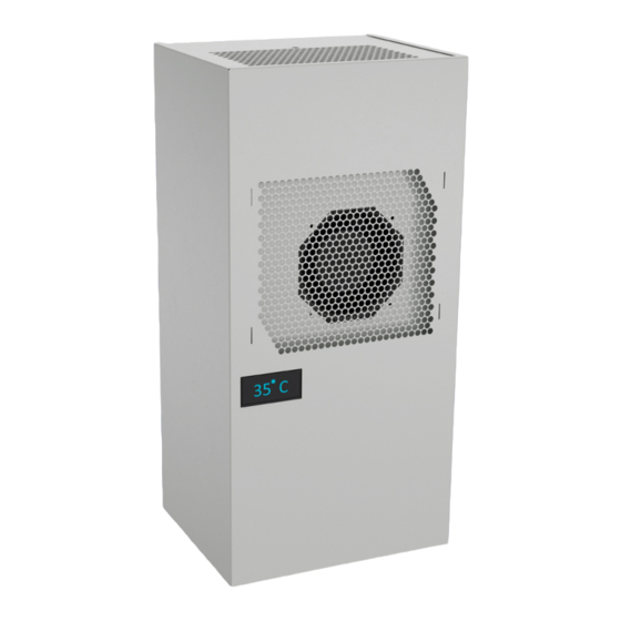
13. Controller The unit is equipped with a temperature controller which regulates the function of the air-conditioning cycle. At normal working conditions the display shows the temperature inside the enclosure. The cooling set point for the interior of the enclosure (parameter St / St1) is pre-set at 35°C and can be adjusted between 20°C and 50°C. -
Page 15: Wiring Diagram
14. Wiring Diagram Version No. 1-7 - 01.08.2022 Doc. No. 9943051081 15 / 19... -
Page 16: Taking Into Operation
15. Taking into Operation Attention! The unit can be damaged by lack of lubricant. To ensure that the compressor is adequately lubricated the oil, which has been displaced during transport, must be allowed to flow back into it. The unit must therefore be allowed to stand for at least 30 min. -
Page 17: Transport & Storage
18. Transport & Storage Malfunction due to transport damage On delivery the carton box containing the unit must be examined for signs of transport damage. Any transport damage to the carton box could indicate that the unit itself has been damaged in transit which in the worst case could mean that the unit will not function. -
Page 18: Parts Supplied / Spare Parts / Accessories
19. Parts supplied / Spare parts / Accessories Description Image Instruction manual CE Declaration Mounting template M6 * 16 bolts A6.4 washer M6 toothed washers Lifting hook M8 x 12 PVC washer Drain pipe Female connector Foam tape Accessories: Description Order no. - Page 19 Seifert Systems GmbH Seifert Systems Ltd. Seifert Systems AG Seifert Systems GmbH Seifert Systems Ltd. Seifert Systems Inc. Seifert Systems Pty Ltd. Albert-Einstein-Str. 3 HF09/10 Wilerstrasse 16 Bärnthal 1 Rep. Office 75 Circuit Drive 105 Lewis Road Hal-Far Industrial Estate...
Need help?
Do you have a question about the KG 4305 and is the answer not in the manual?
Questions and answers