Table of Contents
Advertisement
Quick Links
We advise you to read this manual carefully, which contains all the instructions for
maintaining the appliance's aesthetic and functional qualities.
For further information on the product: www.smeg.com
Contents
4
4
8
8
9
9
9
10
10
11
11
12
12
13
14
15
16
17
17
18
19
19
21
24
24
25
26
26
28
29
31
31
34
36
40
41
3
Advertisement
Table of Contents

Related Manuals for Smeg Classica Concerto SSA92MAA9


Summary of Contents for Smeg Classica Concerto SSA92MAA9
-
Page 1: Table Of Contents
5.2 Adaptation to different types of gas 5.3 Positioning 5.4 Electrical connection 5.5 For the installer We advise you to read this manual carefully, which contains all the instructions for maintaining the appliance’s aesthetic and functional qualities. For further information on the product: www.smeg.com... -
Page 2: Instructions
Instructions 1 Instructions • Cleaning and maintenance must not be carried out by 1.1 General safety instructions unsupervised children. Risk of personal injury • Make sure that the flame- spreader crowns are correctly • During use the appliance and positioned in their seats with its accessible parts become their respective burner caps. - Page 3 Instructions • Keep the oven door closed • Before any operation on the during cooking. appliance (installation, maintenance, positioning or • If you need to move food or at movement) always wear PPM. the end of cooking, open the door 5 cm for a few seconds, •...
- Page 4 Instructions • Do not sit on the appliance. • Remove all trays and racks which are not required during • Racks and trays should be cooking. inserted as far as they will go into the side guides. The • Do not cover the bottom of the mechanical safety locks that oven cavity with aluminium or prevent them from being...
- Page 5 Instructions • Do not put empty pans or frying Installation pans on switched on cooking • THIS APPLIANCE MUST NOT zones. BE INSTALLED IN A BOAT OR • Do not use rough or abrasive CARAVAN. materials or sharp metal • This appliance must not be scrapers.
-
Page 6: Manufacturer Liability
Instructions • The adjustment conditions for system safety standards. this appliance are shown on • Use cables withstanding a the gas setting label. temperature of at least 90 °C. • Have the gas connection • The tightening torque of the performed by authorised staff. -
Page 7: Identification Plate
Instructions considered inappropriate. To dispose of the appliance: • Cut the power supply cable and • The appliance is not designed remove it along with the plug. to operate with external timers Power voltage or with remote-control systems. Danger of electrocution 1.4 Identification plate •... -
Page 8: How To Read The User Manual
Instructions 1.7 How to read the user manual 1.8 To save energy This user manual uses the following reading • Only preheat the appliance if the conventions: recipe requires you to do so. Instructions • Unless otherwise indicated on the package, defrost frozen foods General information on this user manual, on safety and final... -
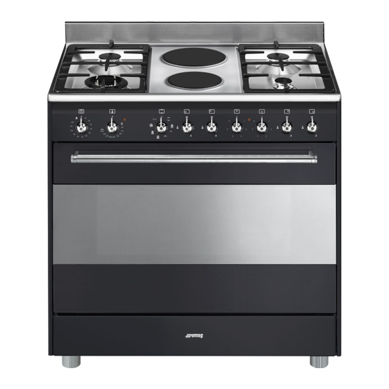
Page 9: Description
Description 2 Description 2.1 General Description 1 Upstand 6 Door 2 Cooking hob 7 Fan 3 Control panel 8 Storage compartment 4 Oven light Rack/tray support frame shelf 5 Seal... -
Page 10: Cooking Hob
Description 2.2 Cooking hob AUX = Auxiliary 1 = Small electric hotplate (1000W) SR = Semi-rapid 2 = Large electric hotplate (1500W) UR = Ultra rapid 2.3 Control panel 1 Timer knob 2 Temperature knob This knob enables manual cooking or the This knob allows you to select the cooking timer to be selected. -
Page 11: Other Parts
Description 4 Function knob 2.4 Other parts The oven's various functions are suitable for Shelves different cooking modes. After selecting the The appliance features shelves to position required function, set the cooking trays and racks at different heights. The temperature using the temperature knob. insertion heights are indicated from the 5 Hob burner knobs bottom upwards (see 2.1 General... -
Page 12: Available Accessories
Description 2.5 Available accessories Tray Some models are not provided with all accessories. WOK ring Useful for collecting fat from foods placed on the rack above. Deep tray Useful when using a wok. Rack Useful for collecting fat from foods placed on the rack above and for cooking pies, pizzas and baked desserts. -
Page 13: Use
3 Use Improper use Risk of damage to surfaces Instructions • Do not cover the bottom of the oven High temperature inside the oven cavity with aluminium or tin foil sheets. during use • If you wish to use greaseproof paper, Danger of burns place it so that it will not interfere with the •... -
Page 14: First Use
Abnormal operation High temperature inside the oven during use Any of the following are considered to be abnormal operation and may require Danger of fire or explosion service: • Do not spray any spray products near • Yellow tipping of the hotplate burner the oven. -
Page 15: Using The Accessories
3.2 Using the accessories 3.3 Using the hob All the appliance’s control and monitoring Ring reducers devices are located together on the front The ring reducers have to be placed on the panel. The burner controlled by each knob hob grids. Make sure they are properly is shown next to the knob. -
Page 16: Using The Electric Hotplates
Correct positioning of the flame- 3.4 Using the electric hotplates spreader crowns and burner caps Preliminary operations Before lighting the hob burners, make sure When switching on the hob for the first time, that the flame-spreader crowns are or if the hob has not been used for a long correctly positioned in their housings with time, to remove any humidity from the their respective burner caps. -
Page 17: Using The Storage Compartment
Advice on energy-saving 3.6 Using the oven • The diameter of the base of the pan must Switching on the oven correspond to the diameter of the cooking zone. 1. Select manual cooking or set the cooking duration using the timer knob. Adjustment is progressive so that the time can also be set to any intermediate value between these numbers. - Page 18 Fan + lower element Fan assisted The combination of the fan with just The operation of the fan, combined the lower heating element allows with traditional cooking, ensures cooking to be completed more consistent cooking even with rapidly. This system is complex recipes.
-
Page 19: Cooking Advice
Advice for cooking with the Grill and the Cooking (and preheating) times Fan with grill are longer with the ECO function. • Meat can be grilled even when it is put into the cold oven or into the preheated When using the ECO function, oven if you wish to change the effect of avoid opening the door during the cooking. - Page 20 • If the dessert collapses when it comes out of the oven, on the next occasion reduce the set temperature by about 10°C, selecting a longer cooking time if necessary. • While cooking desserts or vegetables, excessive condensation may form on the glass.
- Page 21 Cooking information table Runner Weight Temperature Food Function position from Time (minutes) (Kg) (°C) the bottom Lasagne 3 - 4 Static 220 - 230 45 - 50 Pasta bake 3 - 4 Static 220 - 230 45 - 50 Roast veal Turbo/Fan assisted 180 - 190 90 - 100...
-
Page 22: Cleaning And Maintenance
Cleaning and maintenance 4 Cleaning and maintenance Cleaning the hob 1. Pour some non-abrasive detergent on a Instructions damp cloth and wipe down the surfaces. 2. Rinse thoroughly. Improper use 3. Dry with a soft cloth or a microfibre cloth. Risk of damage to surfaces Cooking hob pan stands •... -
Page 23: Removing The Door
Cleaning and maintenance Cleaning the igniters and thermocouples 4.2 Removing the door For easier cleaning, the door can be • If necessary, clean the igniters and removed and placed on a canvas. thermocouples with a damp cloth. To remove the door proceed as follows: •... -
Page 24: Cleaning The Door Glazing
Cleaning and maintenance 3. To reassemble the door, put the hinges in 4.4 Removing the internal glass panes the relevant slots in the oven, making sure For easier cleaning the door internal glass that grooved sections A are resting panes can be disassembled. completely in the slots. - Page 25 Cleaning and maintenance 4. Clean the external glass pane and the Removing the rack/tray support frames panes previously removed. Use Removing the rack/tray support frames absorbent kitchen roll. In case of enables the sides to be cleaned more stubborn dirt, wash with a damp sponge easily.
-
Page 26: Vapor Clean
Cleaning and maintenance 4.5 Vapor Clean • Pour approximately 40 cc of water into the tray. Make sure it does not overflow Vapor Clean is an assisted out of the cavity. cleaning procedure which facilitates the removal of dirt. Thanks to this process, it is possible to clean the inside of the oven very easily. -
Page 27: Extraordinary Maintenance
Cleaning and maintenance Vapor Clean setting 4.6 Extraordinary maintenance 1. Turn the function knob to the symbol Installing and removing the seal and the temperature knob to the symbol To remove the seal: • Unhook the clips in the 4 corners and in the centre, then pull the seal. - Page 28 Cleaning and maintenance 4. Slide out and remove the light bulb. Replacing the internal light bulb Live parts Danger of electrocution • Unplug the appliance. The oven is fitted with a 40W light bulb. Do not touch the halogen light bulb directly with your fingers, but 1.
-
Page 29: Installation
Installation 5 Installation Connection with a rubber hose Verify that all following conditions are met: 5.1 Gas connection • the hose is fixed to the hose connection with safety clamps; Gas leak • no part of the hose is in contact with hot Danger of explosion walls (max. - Page 30 Installation After having tightened the hose Carefully screw the connector 3 to the gas connector(s), push the gas hose 6 onto the connector 1 of the appliance, placing the hose connector and secure it with the clamp 5 seal 2 between them. that is compliant with the standard in force.
- Page 31 Installation Connection with a steel hose with conical Room ventilation fitting The appliance should be installed in rooms Make the connection to the gas mains that have a permanent air supply in using a continuous wall steel hose whose accordance with the standards in force. The specifications comply with the applicable room where the appliance is installed must standard.
-
Page 32: Adaptation To Different Types Of Gas
Installation When the job is complete, the installer must 5.2 Adaptation to different types of issue a certificate of conformity. In case of operation with other types of gas, the burner nozzles must be changed and the minimum flame adjusted on the gas cocks. - Page 33 Installation Adjusting the minimum setting for natural Adjusting the minimum setting for LPG or town gas Tighten the screw located at the side of the Light the burner and turn it to the minimum tap rod clockwise all the way. position.
-
Page 34: Positioning
Installation 5.3 Positioning General information This appliance may be installed next to Heavy appliance walls, one of which must be higher than the Crushing hazard worktop, at a minimum distance of 50 mm from the side of the appliance, as shown in •... - Page 35 Installation Appliance overall dimensions 900 mm 600 mm B - Class 2 subclass 1 min. 150 mm (Built-in appliance) 900 - 915 mm 750 mm 450 mm 900 mm Minimum distance from side walls or other flammable material. Minimum cabinet width (=A). C - Class 2 subclass 1 (Built-in appliance) The appliance must be installed by...
- Page 36 Installation Dimensions of the appliance: locations of Positioning and levelling gas and electric connections (mm) Heavy appliance Risk of damage to the appliance • Insert the front feet first and then the rear ones. • After making the gas and electrical connections, screw on the four feet supplied with the appliance.
- Page 37 Installation Wall fixing 4. Mark the wall in the position where the hole is to be drilled. 1. Turn the screw placed behind the cooktop near the gas connection. 5. Drill the hole and insert a wall plug. 2. Attach the chain to the cooker with the screw just removed.
-
Page 38: Electrical Connection
Installation 5.4 Electrical connection Assembling the upstand The upstand provided is an Power voltage integral part of the product. It must Danger of electrocution be fastened to the appliance prior to installation. • Have the electrical connection performed by authorised technical The upstand must always be positioned and personnel. -
Page 39: For The Installer
Installation The appliance can work in the following 5.5 For the installer modes: • The plug must remain accessible after the • 220-240 V 1N~ installation is complete. Do not kink or trap the mains connection cable. • The appliance must be fitted according to the installation diagrams.
Need help?
Do you have a question about the Classica Concerto SSA92MAA9 and is the answer not in the manual?
Questions and answers