
Related Manuals for Doepke DFA


Summary of Contents for Doepke DFA
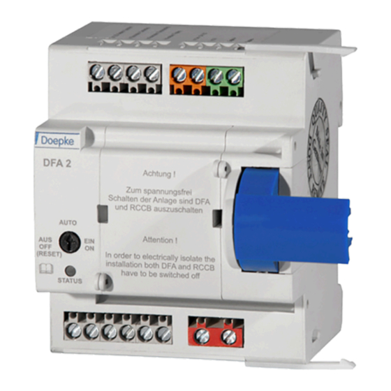
- Page 1 Doepke Montage- und Bedienungsanleitung Operating instructions Fernantrieb DFA Remote actuator DFA...
- Page 2 Doepke Montage- und Bedienungsanleitung Fernantrieb DFA Operating instructions Remote actuator DFA Artikelnummer 3930131 | Stand: 09/2013...
-
Page 3: Table Of Contents
General Description ........14 Vorbereitung ..........4 Preparation ..........14 2.1. Vorbereitung der Fernauslösung ..4 2.1. Preparation for Remote Trip Facility 14 Montage und Inbetriebnahme des DFA ..5 Installation and Commissioning the DFA ..15 3.1. Spannungsversorgung .......6 3.1. Power Supply ........16 3.2. Steuereingänge ........6 3.2. -
Page 4: Allgemeine Beschreibung
DFA problemlos an den Dupline-Bus angeschlossen werden kann. Beim DFA-DI handelt es sich um eine kleine Platine, die einfach in den DFA eingesteckt wird. Damit lassen sich dann ebenfalls die oben genannten Funktionen aus der Ferne aufrufen und die Schaltpositionen anzeigen. -
Page 5: Montage Und Inbetriebnahme Des Dfa
Montage und Inbetriebnahme des DFA Die Montage darf nur durch eine autorisierte Fachkraft vorgenommen werden. Zunächst sind die beiden beiliegenden Rasthaken seitlich so in den DFA einzuclipsen, dass die Rast- nasen zum RCCB zeigen. Zur Montage des Fernantriebes DFA wird dieser links neben dem RCCB platziert. Anschließend wer- den beide Geräte so zusammengeschoben, dass der Knebel des RCCBs vom Mitnehmerhebel des... -
Page 6: Spannungsversorgung
Nach einem fehlgeschlagenen Auslöseversuch, d. h., wenn der Blinkcode 2 ausgegeben wird, sollte ggf. ein weiterer Auslöseversuch – wie bei herkömmlich betriebenen RCCBs auch – erst nach ca. 30 Sekunden durchgeführt werden, um den Prüfstromkreis des DFA nicht zu überlasten. -
Page 7: Schaltausgänge
Über die Relaiskontakte lassen sich kleinere Lasten direkt oder größere Lasten über Installationsrelais schalten. Alle Relais haben mit der Klemme 11 einen gemeinsamen Bockpol. Hinweis: Tritt im DFA ein Fehler auf oder fällt die Betriebsspannung des DFA aus, so schließen alle drei Relaiskontakte, um auf diesen Umstand hinzuweisen. -
Page 8: Bedienungsanleitung
Fehler im RCCB-Stromkreis noch vor, wird kein weiterer Einschaltversuch vorgenom- men. Der DFA wird blockiert und führt keine Schaltbefehle mehr aus, was durch den Blinkcode 4 sig- nalisiert wird. Um die Blockade aufzuheben, muss der DFA kurzzeitig ausgeschaltet werden (RESET). -
Page 9: Blinkcodes
0,1 s ein / 0,9 s aus automatische Einschaltung LED-Takt: 1 s ein / 1 s aus fehlgeschlagen (blockiert) Der Blinkcode 2 hat die höchste Priorität und lässt sich nur durch kurzzeitiges Ausschalten (RESET) des DFA mittels Drehschalter oder kurzes Trennen von der Betriebsspannung zurücksetzen. -
Page 10: Verdrahtung
(DC+) RCCB ausgeschaltet (DC-) RCCB ausgelöst Dupline+ (D+) optional Fernauslösung Lx Dupline- (D-) optional Fernauslösung N Bei der Verdrahtung des DFA ist unbedingt auf Spannungsfreiheit aller Leitungen zu achten! Die Spannungsversorgung des DFA darf nicht über den „betätigten“ RCCB erfolgen. -
Page 11: Verdrahtung Der Fernauslösung
Dies ist eine Adobe® Illustrator®-Datei, die ohne PDF-Inhalt Wird bei einem betätigten RCCB die Fernauslösefunktion gewünscht, so ist er wie folgt elektrisch mit gespeichert wurde. dem DFA zu verbinden: Damit diese Datei in anderen Anwendungen platziert oder geö net werden kann, sollte sie erne Adobe Illustrator mit der aktivierten Option PDF-kompatible Datei erstellen gespeichert werden. -
Page 12: Technische Daten
400 ms Halbleiterausgänge nicht kurzschlussfest – Vorwiderstand notwendig! Status-LED Spannung 21,6 V 24,0 V 26,4 V Nennstrom 50 mA Dupline (optional) Stromaufnahme aus DFA 5 mA Stromaufnahme aus Dupline 350 µA Eingangskanäle Ausgangskanäle Anschlüsse Zugbügelklemmen Klemmbereich 0,4 mm Ø 2,5 mm²... -
Page 13: Garantie
Max. 85 % (Betauung nicht zulässig) Schutzart IP 20 Normen DIN EN 50557, DIN EN 55014-1 Artikelnummern / Zubehör Fernantrieb DFA 2 / DFA 2-1 09 100 110 / 09 100 112 Versorgungsnetzteil RK 24 09 980 654 Dupline-Schnittstelle DFA-DI 09 100 102 * Die zulässige Betriebstemperatur des montierten RCCB ist zu beachten. -
Page 14: General Description
(1 normally open contact each with common pole). The DFA can be de-activated with the aid of the rotary switch on the enclosure cover, so that it can- not be accidentally activated from a remote location, e. g. during maintenance work at the distribution board. -
Page 15: Installation And Commissioning The Dfa
Installation and Commissioning the DFA Installation may only be carried out by an authorized, trained technician. Firstly the two enclosed snap-on brackets have to be inserted into the side of the DFA so that the snap- on lugs point towards the residual current breaker. -
Page 16: Power Supply
If the RCCB does not trip (toggle of the RCCB not in central position) the status LED will signal flash code 2 (see “Flash Codes”, p. 19). This can be reset by briefly switching the DFA off with the rotary switch on the enclosure cover (RESET) or by disconnecting the DFA from the operating voltage for a short time. -
Page 17: Switching Outputs
All relays have a common pole (at terminal 11). Note: If the DFA develops a fault, or if the operating voltage of the DFA fails, all 3 relay contacts will close in order to alert to this situation. -
Page 18: Operating Instructions
This status will only be reset if – in the interim – a connection/disconnection or tripping has been requested, or if the DFA has been briefly switched off (RESET). But if a trip does not occur until 2 seconds after the automatic reconnection process, another reconnection attempt will be made after 15 seconds. -
Page 19: Flash Codes
0,1 s on / 0,9 s off automatic connection LED sequence: 1 s on / 1 s off failed (blocked) Flash code 2 has the highest priority and can only be reset by briefly switching off the DFA (RESET) for a short time. -
Page 20: Wiring
Lx Dupline+ (D+) optional output: remote trip N Dupline- (D-) optional While so doing it must be ensured that all leads are dead. The power supply of the DFA must not be realized via the switched RCCB. -
Page 21: Wiring For Remote Trip Facility
Dies ist eine Adobe® Illustrator®-Datei, die ohne PDF-Inhalt If the remote trip function is required for an actuated RCCB, the RCCB should be electrically linked to gespeichert wurde. the DFA as follows: Damit diese Datei in anderen Anwendungen platziert oder geö net werden kann, sollte sie erne Adobe Illustrator mit der aktivierten Option PDF-kompatible Datei erstellen gespeichert werden. -
Page 22: Technical Data
– series resistor needed! status LED voltage 21,6 V 24,0 V 26,4 V rated current 50 mA Dupline (optional) power consumption (DFA ) 5 mA power consumption (Dupline) 350 µA input channels output channels Terminals type screw terminal with strain-relief clamp terminal cross-section 0,4 mm Ø... -
Page 23: Guarantee
85 % (exposure to dew not permissible) type of protection IP 20 installation regulations DIN EN 50557, DIN EN 55014-1 Article numbers / accessories remote actuator DFA 2 09 100 110 power supply unit RK 24 09 980 654 Dupline interface DFA-DI 09 100 102 * Mind the maximum permissible temperature of the mounted RCCB. - Page 24 Satz- und Druckfehler sowie technische Änderungen vorbehalten / subject to technical changes and misprints Doepke Schaltgeräte GmbH & Co. KG | Stellmacherstraße 11 | D-26506 Norden | Tel. +49 4931 1806-0 | E-Mail: info@doepke.de | Internet: www.doepke.de...
Need help?
Do you have a question about the DFA and is the answer not in the manual?
Questions and answers