
Subscribe to Our Youtube Channel
Related Manuals for Atomic Zombie LodeRunner


Summary of Contents for Atomic Zombie LodeRunner
- Page 1 Build the LodeRunner Delta Trike Another Atomic Zombie Extreme Machines Adventure ™ All content copyright Atomic Zombie™ Extreme Machines. All rights reserved. www.ATOMICZOMBIE.com...
-
Page 2: Table Of Contents
INSTALLING CRANK SET AND CHAIN ..................... 114 BUILDING SEAT MOUNTS ........................117 STEERING ..............................120 INSTALLING LIGHTS..........................137 PRIMING AND PAINTING ........................138 INSTALLING BRAKE CABLES......................140 BUILDING A CARGO BOX........................143 All content copyright Atomic Zombie™ Extreme Machines. All rights reserved. www.ATOMICZOMBIE.com... -
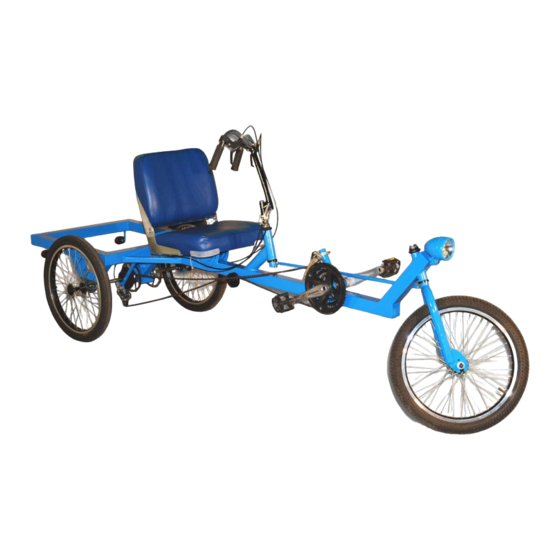
Page 3: About The Loderunner Delta Trike
Because the seat is at a height similar to that of an automobile, the LodeRunner is easy to get into and puts you at eye level to many motorized vehicles on streets and roads. The LodeRunner weighs under 80 pounds fully built, which is less than a single truck wheel, yet it can easily carry a load of 500 pounds. -
Page 4: Building The Rear Frame Box
Building the Rear Frame Box Figure 1 – Tubing sections for the rear frame box Most of the LodeRunner frame is made from 2 inch diameter mild steel square tubing with a 1/16 inch wall thickness. This tubing can be ordered from most steel suppliers and is very easy to cut and weld. - Page 5 4 angles again. If your frame is not square, it will be easy to force it into shape while there are only a few tack welds holding it together. All content copyright Atomic Zombie™ Extreme Machines. All rights reserved. www.ATOMICZOMBIE.com...
- Page 6 If your frame seems “warped”, then you can probably bang it back into shape by hitting it with a rubber mallet or block of wood. All content copyright Atomic Zombie™ Extreme Machines. All rights reserved. www.ATOMICZOMBIE.com...
- Page 7 The order of operations is very important when welding a joint because cooling weld metal tends to contract, which can cause alignment problems. If you weld the most critical side of a joint last, distortion is kept to a minimum. All content copyright Atomic Zombie™ Extreme Machines. All rights reserved. www.ATOMICZOMBIE.com...
- Page 8 When you are finished welding and the tubing has cooled, check the 90 degree corners to ensure they are still within a few degrees. All content copyright Atomic Zombie™ Extreme Machines. All rights reserved. www.ATOMICZOMBIE.com...
- Page 9 The inside corner does nothing except keep out moisture, so it does not need to be a large weld – just enough to seal the joint. All content copyright Atomic Zombie™ Extreme Machines. All rights reserved. www.ATOMICZOMBIE.com...
-
Page 10: Building Rear And Main Boomtube
LodeRunner to be setup efficiently to practically any size rider. The main boom is a length of 2 inch square tubing cut to a length of 58 inches. -
Page 11: Building Truss Tubes
¾ and 1 inch in diameter for these tubes. The truss tubes shown in Figure 8 are ¾ inch square tubes cut to a length of 7 inches. All content copyright Atomic Zombie™ Extreme Machines. All rights reserved. www.ATOMICZOMBIE.com... - Page 12 90 degree angle. Once the truss tubes are solidly tack welded in place, welding heat will not affect the alignment of the main boom as you complete the joints. Figure 9 shows the top of the frame. All content copyright Atomic Zombie™ Extreme Machines. All rights reserved. www.ATOMICZOMBIE.com...
- Page 13 90 degree angle with the rear frame box, so the main boom joints can all be welded without risk of heat distortion. All content copyright Atomic Zombie™ Extreme Machines. All rights reserved. www.ATOMICZOMBIE.com...
- Page 14 11. An experienced welder knows instinctively which side to weld first and may even use distortion as an advantage to fix a misaligned frame. “Using the force” is not just a rule for Jedi knights! All content copyright Atomic Zombie™ Extreme Machines. All rights reserved. www.ATOMICZOMBIE.com...
- Page 15 If you cannot weld the inside corners of the truss tube joints, then just leave them, as they do not add any strength to the frame. All content copyright Atomic Zombie™ Extreme Machines. All rights reserved. www.ATOMICZOMBIE.com...
-
Page 16: Front Frame Tube And Forks
If you can find 14 or 15 inches of suitable round tubing, it could also be used, but be advised that cutting and welding round tubing is a lot more difficult. All content copyright Atomic Zombie™ Extreme Machines. All rights reserved. www.ATOMICZOMBIE.com... - Page 17 Front Tube & Forks Figure 14 – Choosing 20 inch front forks The LodeRunner has a 20 inch front wheel, so you will need a decent pair of 20 inch front forks and a matching head tube with all of the hardware as shown in Figure 14.
- Page 18 Remember, bearings go into the cups “balls first”. Correctly assembled, the forks should easily spin around in the head tube with all the hardware installed. All content copyright Atomic Zombie™ Extreme Machines. All rights reserved. www.ATOMICZOMBIE.com...
-
Page 19: Creating The Head Tube
Figure 16. This also makes it easy to drop in a front hub motor, which requires a larger dropout slot than a regular bicycle. Creating the Head Tube All content copyright Atomic Zombie™ Extreme Machines. All rights reserved. www.ATOMICZOMBIE.com... - Page 20 Figure 18 – Getting the ground clearance set up The LodeRunner has a ground clearance of 15 inches as measured from the underside of the frame to the ground. This height was chosen to keep a safe stance in traffic and to allow the top of the cargo frame to clear all of the brake All content copyright Atomic Zombie™...
- Page 21 2 x 4s to get the required 15 inches of ground clearance. Drawing 1 – The head tube angle is 64 degrees The LodeRunner has a head tube angle of 64 degrees. As shown in Drawing 1, head tube angle is measured by extending a line through the center of the head tube to the ground.
- Page 22 Figure 19 so that it crosses the head tube in the center. The head tube will actually pass through a hole in the front boom as will soon be shown. All content copyright Atomic Zombie™ Extreme Machines. All rights reserved. www.ATOMICZOMBIE.com...
- Page 23 Figure 21 – Marking the head tube line on the front tube All content copyright Atomic Zombie™ Extreme Machines. All rights reserved. www.ATOMICZOMBIE.com...
- Page 24 The line is drawn on both side of the head tube as shown in Figure 22. Once these lines are transferred to the top of the tube, it will be easy to create the holes that the head tube must pass through. All content copyright Atomic Zombie™ Extreme Machines. All rights reserved. www.ATOMICZOMBIE.com...
- Page 25 64 degree angle. Don’t worry about the extra tubing sticking out past the head tube; this will be dealt with later. All content copyright Atomic Zombie™ Extreme Machines. All rights reserved. www.ATOMICZOMBIE.com...
- Page 26 Figure 24, you start by drilling a bunch of 1/8 inch holes along the inside of the line, trying to get them as close together as you can. All content copyright Atomic Zombie™ Extreme Machines. All rights reserved. www.ATOMICZOMBIE.com...
- Page 27 “lid”, just like the lid on a can. The hole looks more like a shark’s mouth at this point (Figure 25), but that’s nothing the round file won’t fix in a few minutes. All content copyright Atomic Zombie™ Extreme Machines. All rights reserved. www.ATOMICZOMBIE.com...
- Page 28 Figure 26 shows the holes before they were made oval, and you can see the difference of you compare them to the next photo. All content copyright Atomic Zombie™ Extreme Machines. All rights reserved. www.ATOMICZOMBIE.com...
- Page 29 Figure 27. Because you are working the hole with a hand file, it is easy to get the head tube gap down to a minimum, which will make welding very easy. All content copyright Atomic Zombie™ Extreme Machines. All rights reserved. www.ATOMICZOMBIE.com...
- Page 30 Don’t worry about military precision with the head tube angle – a few degrees either way will not make any difference in the handling characteristics of the trike. All content copyright Atomic Zombie™ Extreme Machines. All rights reserved. www.ATOMICZOMBIE.com...
- Page 31 Also, you will do the same thing to the open end of the main boom tube, so cut out two caps and duplicate the process for both tubes. All content copyright Atomic Zombie™ Extreme Machines. All rights reserved. www.ATOMICZOMBIE.com...
- Page 32 Weld the tubing cap all the way around as shown in Figure 30. Don’t worry about doing a fancy weld here, as it will be ground clean. Figure 31 – Tubing cap completed All content copyright Atomic Zombie™ Extreme Machines. All rights reserved. www.ATOMICZOMBIE.com...
- Page 33 The head tube should extend an equal distance out of the top and bottom of the hole. All content copyright Atomic Zombie™ Extreme Machines. All rights reserved. www.ATOMICZOMBIE.com...
- Page 34 90 degrees. Figure 34 – Tack welding the front tube to the main boom All content copyright Atomic Zombie™ Extreme Machines. All rights reserved. www.ATOMICZOMBIE.com...
- Page 35 If an error is obvious to you, it will also be obvious to others, so don’t be afraid to take out that grinder and fix your errors! All content copyright Atomic Zombie™ Extreme Machines. All rights reserved. www.ATOMICZOMBIE.com...
- Page 36 “coax” it back into shape with a length of 2 x 4 or a large rubber mallet. A huge rubber mallet is another tool that I often use. Figure 37 – Completing the front tube joint All content copyright Atomic Zombie™ Extreme Machines. All rights reserved. www.ATOMICZOMBIE.com...
- Page 37 Most of the force is carried by the front and rear joint, so you can grind the sides of the joint to make them look neat and clean. All content copyright Atomic Zombie™ Extreme Machines. All rights reserved. www.ATOMICZOMBIE.com...
-
Page 38: Bearing Support Tubes
Read ahead a bit to understand how this system works. Following drawing 2, you will need to cut two tubes marked “A” and 4 tubes marked “B” to create both bearing supports. All content copyright Atomic Zombie™ Extreme Machines. All rights reserved. www.ATOMICZOMBIE.com... - Page 39 Figure 39 shows one of the tubes that will make up one of the four tubes marked “B” in Drawing 2. I used the folded paper method to check the angles. All content copyright Atomic Zombie™ Extreme Machines. All rights reserved. www.ATOMICZOMBIE.com...
- Page 40 You will probably need to place them both in the vice and do some grinding to make All content copyright Atomic Zombie™ Extreme Machines. All rights reserved. www.ATOMICZOMBIE.com...
- Page 41 Figure 43 – Both bearing supports are equal in height After a little tandem grinding in the vice, both bearing supports are exactly the same height when stood together as shown in Figure 43. The top All content copyright Atomic Zombie™ Extreme Machines. All rights reserved. www.ATOMICZOMBIE.com...
- Page 42 6 feet squared, and place the wheels in the center to carry a thousand pounds! Of course, a vehicle of that capacity might not be safe on the street, and would need some serious brakes. All content copyright Atomic Zombie™ Extreme Machines. All rights reserved. www.ATOMICZOMBIE.com...
- Page 43 The sides of the joint are welded to the rear frame box as shown in Figure 46, completing the installation of the bearing supports. If you flip the frame over and stand it on the bearing supports, the rear frame should be perfectly level. All content copyright Atomic Zombie™ Extreme Machines. All rights reserved. www.ATOMICZOMBIE.com...
-
Page 44: Installing Pillow Block Bearings And Axle
The bearings are sealed for life and will never need grease. All content copyright Atomic Zombie™ Extreme Machines. All rights reserved. www.ATOMICZOMBIE.com... - Page 45 Most of the bearing bodies have slightly slotted holes, so there is a bit of room for adjustment if necessary. All content copyright Atomic Zombie™ Extreme Machines. All rights reserved. www.ATOMICZOMBIE.com...
- Page 46 Figure 49 shows the marked bearing holes, ready for bolts to be welded. All content copyright Atomic Zombie™ Extreme Machines. All rights reserved. www.ATOMICZOMBIE.com...
- Page 47 Choose a bolt size that fits the pillow block bearing perfectly with as little play as possible. As shown in Figure 50, you will also need eight washers and eight matching nuts. All content copyright Atomic Zombie™ Extreme Machines. All rights reserved. www.ATOMICZOMBIE.com...
- Page 48 The bolt segments need to have enough length to allow the nut and washer to fit as shown in Figure 51. You could probably just cut all of the segments to 2 inches, as that would be plenty of bolt length. All content copyright Atomic Zombie™ Extreme Machines. All rights reserved. www.ATOMICZOMBIE.com...
- Page 49 Welding around a bolt is great practice, and once you improve your “welding guru” skills, you can finish the entire joint without stopping. All content copyright Atomic Zombie™ Extreme Machines. All rights reserved. www.ATOMICZOMBIE.com...
- Page 50 If your bearings have a long and short ring face (usually to hold the set screws), then face the long side outwards as shown in Figure 53. All content copyright Atomic Zombie™ Extreme Machines. All rights reserved. www.ATOMICZOMBIE.com...
- Page 51 To drive both rear wheels, you would need a geared differential - a complex setup that splits All content copyright Atomic Zombie™ Extreme Machines. All rights reserved. www.ATOMICZOMBIE.com...
- Page 52 Figure 55 is at least 1/8 inch thick, and is cut large enough so that both pillow block bearings can sit on top. Just like the bearing mounting tubes, four bolt segments will be welded in place to hold the bearings to the plate. All content copyright Atomic Zombie™ Extreme Machines. All rights reserved. www.ATOMICZOMBIE.com...
- Page 53 The plate only needs to be as large as the two bearing bodies as shown in Figure 56. Also shown are four more bolt segments ready to be welded to the plate to hold the bearings in place. All content copyright Atomic Zombie™ Extreme Machines. All rights reserved. www.ATOMICZOMBIE.com...
- Page 54 The inner bearing assembly is shown complete in Figure 57. If your bearings have a long and short ring face (usually to hold the set screws), then face the long side outwards as shown in Figure 57. All content copyright Atomic Zombie™ Extreme Machines. All rights reserved. www.ATOMICZOMBIE.com...
- Page 55 This tube will joint the inner bearing support plate to the frame, and will be cut to the correct size by using the solid axle as a guide. All content copyright Atomic Zombie™ Extreme Machines. All rights reserved. www.ATOMICZOMBIE.com...
- Page 56 You may need to play around with the bearing races to get them to align while you slide the axle through them. Don’t worry, once they straighten, it won’t be as difficult to get them installed next time. All content copyright Atomic Zombie™ Extreme Machines. All rights reserved. www.ATOMICZOMBIE.com...
- Page 57 Figure 60 shows a marker line made by tracing the edge of the center bearing assembly along the face of the tube. All content copyright Atomic Zombie™ Extreme Machines. All rights reserved. www.ATOMICZOMBIE.com...
- Page 58 Once cut, it should fit into place as shown in Figure 61, allowing you to trace around the tube to while it is placed in the center of the bearing support plate. All content copyright Atomic Zombie™ Extreme Machines. All rights reserved. www.ATOMICZOMBIE.com...
- Page 59 45 degree cut end of the tube drops flat on the frame. If everything checks out, then remove the assembly for final welding. All content copyright Atomic Zombie™ Extreme Machines. All rights reserved. www.ATOMICZOMBIE.com...
- Page 60 The support tube is welded to the bearing support plate as shown in Figure 63 once it has been checked for a proper fit. Once welded, place the bearings and assembly back on the axle. All content copyright Atomic Zombie™ Extreme Machines. All rights reserved. www.ATOMICZOMBIE.com...
- Page 61 45 degree end of the support tube fall onto the frame, and then make a few corner tack welds to hold it in place. All content copyright Atomic Zombie™ Extreme Machines. All rights reserved. www.ATOMICZOMBIE.com...
- Page 62 If you placed your ground clamp on the axle and tried to weld the frame, the bearings would be badly damaged from the current that would flow though them. All content copyright Atomic Zombie™ Extreme Machines. All rights reserved. www.ATOMICZOMBIE.com...
- Page 63 Remember not to pound out the axles with a hammer unless it is rubber, or by using a block of wood over the end. All content copyright Atomic Zombie™ Extreme Machines. All rights reserved. www.ATOMICZOMBIE.com...
- Page 64 Figure 67 shows the two axles after cutting and reinstalling them. Now, let’s move on to the part that you have either been dreading or dying to try – the wheel building process. All content copyright Atomic Zombie™ Extreme Machines. All rights reserved. www.ATOMICZOMBIE.com...
-
Page 65: Building The Wheels
Figure 68 – You will need a pair of BMX wheels One of the most unique features of the LodeRunner is that it has no rear hubs. The flanges that hold the spokes are actually part of the rear axles, so this greatly simplifies the design and saves the builder a lot of money that would otherwise go to purchasing expensive aluminum hubs to be machined. -
Page 66: Hub Flanges
The hub flanges are nothing more than steel discs made from 1/8 inch thick steel plate or flat bar. The goal is to copy the hub flanges that came from All content copyright Atomic Zombie™ Extreme Machines. All rights reserved. www.ATOMICZOMBIE.com... - Page 67 My flanges were 2.25 inches in diameter, so I traced four circles onto some 1/8 inch All content copyright Atomic Zombie™ Extreme Machines. All rights reserved. www.ATOMICZOMBIE.com...
- Page 68 Figure 71. I don’t own a bench grinder, but if you have one, it will do this job perfectly. Figure 72 – The disc on the right is perfectly round All content copyright Atomic Zombie™ Extreme Machines. All rights reserved. www.ATOMICZOMBIE.com...
- Page 69 Using the minimalist approach, I used multiple drill bits and a hand drill. Figure 73 shows the 4 drilled discs, ready for the larger bits. All content copyright Atomic Zombie™ Extreme Machines. All rights reserved. www.ATOMICZOMBIE.com...
- Page 70 1/8 bit. Stepping up one size at a time make a much more accurate hole, which is what a step drill bit will do for you. All content copyright Atomic Zombie™ Extreme Machines. All rights reserved. www.ATOMICZOMBIE.com...
- Page 71 If you do not have the software or tools to make a template, ask a computer savvy pal to make them for you in exchange for a ride in your new trike. All content copyright Atomic Zombie™ Extreme Machines. All rights reserved. www.ATOMICZOMBIE.com...
- Page 72 It took about 15 minutes of filing per disc to get the holes perfectly centered and to the correct diameter. Figure 78 – Flanges ready for spoke hole drilling All content copyright Atomic Zombie™ Extreme Machines. All rights reserved. www.ATOMICZOMBIE.com...
- Page 73 Figure 79 for those of you who do not own a drill press (myself included). Just bolt the flanges to the edge of your workbench and “go to town” with the hand drill. All content copyright Atomic Zombie™ Extreme Machines. All rights reserved. www.ATOMICZOMBIE.com...
- Page 74 Figure 80, beveling the holes is as simple as pushing them lightly against a spinning 3/16 inch drill bit just to take off the sharp edges. This process is done on both side of the disc, and takes only a few minutes. All content copyright Atomic Zombie™ Extreme Machines. All rights reserved. www.ATOMICZOMBIE.com...
- Page 75 Even the cheapest bicycle hubs have beveled holes. Figure 82 – Testing a spoke in the hole All content copyright Atomic Zombie™ Extreme Machines. All rights reserved. www.ATOMICZOMBIE.com...
- Page 76 The hub flanges will be welded directly to the rear axles, creating a clean looking and incredibly strong rear wheel assembly. Again, you will be following the original design of the hub you are copying, so place it up against All content copyright Atomic Zombie™ Extreme Machines. All rights reserved. www.ATOMICZOMBIE.com...
- Page 77 If you are welding in a vice, then this is not a concern. All content copyright Atomic Zombie™ Extreme Machines. All rights reserved. www.ATOMICZOMBIE.com...
- Page 78 Once spinning true, make a larger weld across from the original tack weld as shown in Figure 86. All content copyright Atomic Zombie™ Extreme Machines. All rights reserved. www.ATOMICZOMBIE.com...
- Page 79 Do not weld the other side of the joint on the inside flange. It is not necessary, and will only make it more difficult to center the axle and disc brake later. All content copyright Atomic Zombie™ Extreme Machines. All rights reserved. www.ATOMICZOMBIE.com...
-
Page 80: Outer Flange
This line is then used as a guide when you make the initial tack weld. Do not do any more welding until you check the offset. All content copyright Atomic Zombie™ Extreme Machines. All rights reserved. www.ATOMICZOMBIE.com... - Page 81 Yes, you could also turn the face down in a lathe of you are lucky enough to have such tools. Figure 89 shows the results of cleaning up the face of the flange with a flap disc. All content copyright Atomic Zombie™ Extreme Machines. All rights reserved. www.ATOMICZOMBIE.com...
-
Page 82: Painting Hub Axles
There is no ugly bolt or cotter pin hanging off the end of the hub, just nice a nice smooth face. All content copyright Atomic Zombie™ Extreme Machines. All rights reserved. www.ATOMICZOMBIE.com... -
Page 83: Truing And Spoking
I decided to install the spokes at this stage, and then continue building the rest of the LodeRunner. I decided to true the wheels once the paint was curing, since that takes a few days. The wooden handle shown in Figure 91 is actually being used as a guide to check the trueness of the rim as I work on the spokes. - Page 84 Aggressive tread tires should never be used on any bicycle that is not planning to traverse the deep woods or up the side of a mountain. Smooth, hard tires roll with much less friction. All content copyright Atomic Zombie™ Extreme Machines. All rights reserved. www.ATOMICZOMBIE.com...
-
Page 85: Building Rear Axles
1/2 inch for the spacer, so test fit the axle into the bearing until there is no less than 1/4 inch clearance between any part of the wheel and the frame. All content copyright Atomic Zombie™ Extreme Machines. All rights reserved. www.ATOMICZOMBIE.com... - Page 86 As shown in Figure 95, a zip disc makes fast work of trimming the axles, which are then beveled slightly using a sanding disc. All content copyright Atomic Zombie™ Extreme Machines. All rights reserved. www.ATOMICZOMBIE.com...
- Page 87 There should be no side-to-side play in the axle at all. All content copyright Atomic Zombie™ Extreme Machines. All rights reserved. www.ATOMICZOMBIE.com...
- Page 88 To remember which way it goes, just tap a few identifying marks using your punch for each side. All content copyright Atomic Zombie™ Extreme Machines. All rights reserved. www.ATOMICZOMBIE.com...
-
Page 89: Free Hub And Disc Brake
Drilling and tapping your own disc brake holes is not difficult though, and the tool you will need can be purchased at any hardware store for a few dollars. All content copyright Atomic Zombie™ Extreme Machines. All rights reserved. www.ATOMICZOMBIE.com... - Page 90 It may actually cost the same to have both parts made identical due to the time it takes to setup a All content copyright Atomic Zombie™ Extreme Machines. All rights reserved. www.ATOMICZOMBIE.com...
- Page 91 You will notice that I actually mounted a BMX freehub on my other adapted so I could later convert the LodeRunner into a tandem vehicle with independent drive for each rider.
- Page 92 Figure 102. Before you drill any holes, read ahead until you completely understand how the transmission and braking system needs to work. All content copyright Atomic Zombie™ Extreme Machines. All rights reserved. www.ATOMICZOMBIE.com...
- Page 93 Figure 101 shows the start of the axle drilling for the left side (brake only) adapter. In my design, I added a BMX freehub for an optional future tandem or motor drive. All content copyright Atomic Zombie™ Extreme Machines. All rights reserved. www.ATOMICZOMBIE.com...
- Page 94 The left side disc brake rotor can be anywhere on the axle, since the disc caliper can be easily adapted anywhere. Basically, keep all drive systems as close to the inner bearings as you can. All content copyright Atomic Zombie™ Extreme Machines. All rights reserved. www.ATOMICZOMBIE.com...
- Page 95 Free Hub & Disc Brake Figure 103 – Creating a disc brake mount The LodeRunner is designed to use a pair of rear disc brakes for maximum stopping power. Disc brakes come in many styles and shapes, but you should have no problem adapting any of them to the frame. I do recommend that you keep both brakes and rotors the same so braking will be smooth and evenly distributed.
- Page 96 The two bolts were welded to the small bits of 3/8 inch tubing to allow adequate clearance of the bodies. All content copyright Atomic Zombie™ Extreme Machines. All rights reserved. www.ATOMICZOMBIE.com...
- Page 97 When the brake is clamped to the disc with both pads over the brake area, this is the optimal alignment point. All content copyright Atomic Zombie™ Extreme Machines. All rights reserved. www.ATOMICZOMBIE.com...
- Page 98 Welding the arm in place with the brake engaged was certainly the best way to ensure proper alignment. All content copyright Atomic Zombie™ Extreme Machines. All rights reserved. www.ATOMICZOMBIE.com...
- Page 99 I wrapped the brake hardware in an old work glove after it was in place so the welding process would not damage the part. Watch out for heat if your brake hardware has plastic parts! All content copyright Atomic Zombie™ Extreme Machines. All rights reserved. www.ATOMICZOMBIE.com...
- Page 100 If you are really in trouble, drill the hole up to the next size to allow a little wiggle room when centering the brakes. All content copyright Atomic Zombie™ Extreme Machines. All rights reserved. www.ATOMICZOMBIE.com...
-
Page 101: Installing The Rear Derailleur
The concept is exactly the same on the LodeRunner, although you will need to get creative to place the derailleur in the correct position. The derailleur shown in Figure 109 is a small bodied road bike style, but any derailleur will work. - Page 102 Rear Derailleur Figure 110 – You won’t need this part anymore The LodeRunner has no stationary threaded rear axle or dropouts, so the slotted arm shown in Figure 110 can be cut form the derailleur. The goal is to place the rear derailleur in the same position over the rear freehub as would normally be, so this arm needs to be cut away in order to achieve this.
- Page 103 Figure 112 shows how the mounting arm places the rear derailleur in the exact position it would be on a normal bicycle. In its relaxed mode, the derailleur is sitting over the smallest chain ring on the freehub. All content copyright Atomic Zombie™ Extreme Machines. All rights reserved. www.ATOMICZOMBIE.com...
- Page 104 (no cable) position. The cable will pull it to the right over the larger chain rings until the limit screw locks it out. All content copyright Atomic Zombie™ Extreme Machines. All rights reserved. www.ATOMICZOMBIE.com...
-
Page 105: Building The Adjustable Bottom Bracket
Building the Adjustable Bottom Bracket Figure 114 – Removing the bottom bracket and seat tube The LodeRunner includes an adjustable bottom bracket so that riders of varying leg lengths can adjust the distance between the seat and pedals for optimum comfort and performance. Moving the bottom bracket is better than moving the seat because the steering system would also have to move with the seat, creating a very complex and difficult design to adjust linkage system. - Page 106 These two plates will form a "vice" that will clamp the bottom bracket to whatever position on the main boom you want. All content copyright Atomic Zombie™ Extreme Machines. All rights reserved. www.ATOMICZOMBIE.com...
- Page 107 Start with a heavy disc and then clean up the shell (including the paint) using a sanding disc. Welding over paint creates horribly toxic fumes that will stink up your work area! All content copyright Atomic Zombie™ Extreme Machines. All rights reserved. www.ATOMICZOMBIE.com...
- Page 108 Keeping the cups installed also protects the threads when welding. All content copyright Atomic Zombie™ Extreme Machines. All rights reserved. www.ATOMICZOMBIE.com...
- Page 109 If the bottom bracket becomes overly distorted, it will be a serious challenge trying to screw the hardware back into the bottom brackets without stripping the threads. All content copyright Atomic Zombie™ Extreme Machines. All rights reserved. www.ATOMICZOMBIE.com...
- Page 110 Figure 119. This will allow you to set the bottom bracket into the correct position for tack welding, as well as ensure that both plates are aligned All content copyright Atomic Zombie™ Extreme Machines. All rights reserved. www.ATOMICZOMBIE.com...
- Page 111 It may be a bit tricky to get the first tack weld in place while holding the bottom bracket in position, but once this is done, the rest is easy. All content copyright Atomic Zombie™ Extreme Machines. All rights reserved. www.ATOMICZOMBIE.com...
- Page 112 Because of the way the clamp system works, there would be no added benefit from welding the inside of the joint anyway. Figure 122 – Welding the clamp plates All content copyright Atomic Zombie™ Extreme Machines. All rights reserved. www.ATOMICZOMBIE.com...
- Page 113 If the holes are not below the line, you will not be able to pass the bolts through both plates because they will hit the frame tubing instead. Figure 124 – Completed bottom bracket assembly All content copyright Atomic Zombie™ Extreme Machines. All rights reserved. www.ATOMICZOMBIE.com...
-
Page 114: Installing Crank Set And Chain
The long side of the axle goes on the right and helps place the chain rings away from the frame. Figure 125 shows the adjustable bottom bracket and crank set installed on the frame. All content copyright Atomic Zombie™ Extreme Machines. All rights reserved. www.ATOMICZOMBIE.com... - Page 115 Cranks & Chain Figure 126 – Putting together the chain The LodeRunner needs a long bicycle chain made up of two or more normal cycle chains to make the distance. I recommend that you purchase chain link tool from your cycle shop, as this will make building chains extremely easy and will not cost much at all.
- Page 116 Yes, you could even hack up another rear derailleur and make someth ut of the small p lastic wheels. Figure 128 – Return chain pulley installed All content copyright Atomic Zombie™ Extreme Machines. All rights reserved. www.ATOMICZOMBIE.com...
-
Page 117: Building Seat Mounts
With such a simple frame design and all of that seating room, you could add just about any kind of seat you wanted to the LodeRunner. I usually make my seats out of foam and wood, but this time I wanted more comfort than anything else, so I hit the local hardware store and found a fishing boat seat on sale for less than $50. - Page 118 Figure 130 shows how this makeshift clamp was made out of the two plates that came with the original seat rotator. Figure 131 – Finding the best seat position and angle All content copyright Atomic Zombie™ Extreme Machines. All rights reserved. www.ATOMICZOMBIE.com...
- Page 119 LodeRunner, a 25 degree decline seemed to be just right. Figure 131 shows how the hacked clamp system hugs the frame as I prop up the seat using a few tubes to test different positions and angles.
-
Page 120: Steering
Steering Figure 133 – Removing the head tube and down tube The LodeRunner has indirect steering, which connects the handlebars to the front forks via rod and ball joints (spherical bearings). Direct steering where the handlebars connect directly to a gooseneck placed in the front fork set would be impossible on a trike which puts the rider so far back from the front wheel. - Page 121 However, do ensure that if there is damage, it has not been done to the stem as well. One thing to All content copyright Atomic Zombie™ Extreme Machines. All rights reserved. www.ATOMICZOMBIE.com...
- Page 122 The bearing race will tap off of the stem if you bang it all the way around with a chipping hammer. All content copyright Atomic Zombie™ Extreme Machines. All rights reserved. www.ATOMICZOMBIE.com...
- Page 123 All content copyright Atomic Zombie™ Extreme Machines. All rights reserved. www.ATOMICZOMBIE.com...
- Page 124 LodeRunner Delta Trike Steering Figure 138 – Control arms and ball joints The LodeRunner steering system will connect the front forks to the handle bars using a pair of control arms and two ball joints (spherical bearings) so that the exact movements of the handle bars will be transferred to the front forks, giving the feel as if you were holding on to handlebars directly connected to the front forks like that of a regular bicycle.
- Page 125 Drawing 5. The rounded area at the base of each control arm will form to the crown area on your front steering All content copyright Atomic Zombie™ Extreme Machines. All rights reserved. www.ATOMICZOMBIE.com...
- Page 126 LodeRunner Delta Trike Steering system and to one of the legs on the LodeRunner's front forks. Look ahead a few steps to see how this works. Figure 140 – Pilot’s control arm installed The pilot’s control arm is welded to the base of the fork stem as shown i Figure 140.
- Page 127 Figure 142 – Parts needed to make the long gooseneck The LodeRunner requires a very unique long and straight gooseneck in order t o mount the handlebars to the steering head tube. You will not find...
- Page 128 In case you need to make a slight adjustment later, you will be able to move the gooseneck up and down slightly just as it was done on a regular bicycle. All content copyright Atomic Zombie™ Extreme Machines. All rights reserved. www.ATOMICZOMBIE.com...
- Page 129 I have found that these old style “Granny bars” are usually perfect for over seat remote steering systems as they curve around you legs to give knee All content copyright Atomic Zombie™ Extreme Machines. All rights reserved. www.ATOMICZOMBIE.com...
- Page 130 If you do need to re place the bearings, only the lower one ill be fixed, but you could simply grease the lower cup and feed the balls in place m anually. All content copyright Atomic Zombie™ Extreme Machines. All rights reserved. www.ATOMICZOMBIE.com...
- Page 131 5 degrees or so of each other in order to make t he linkage work roperly. Follow the usual order of welding operations. Figure 148 – Fork control arm installation All content copyright Atomic Zombie™ Extreme Machines. All rights reserved. www.ATOMICZOMBIE.com...
- Page 132 Figure 149, as you would not want these welds to fail! All content copyright Atomic Zombie™ Extreme Machines. All rights reserved. www.ATOMICZOMBIE.com...
- Page 133 Now you know how far apart the ball joint b olt holes need to be. For any fine tuning, you can simply move the gooseneck in the pilot’s steering tube. All content copyright Atomic Zombie™ Extreme Machines. All rights reserved. www.ATOMICZOMBIE.com...
- Page 134 The control rod will sneak in between the frame and crank arm as shown in Figure 152 once installed. Don’t worry about how close the control rod may be to the crank arm, as your foot can never enter this space. All content copyright Atomic Zombie™ Extreme Machines. All rights reserved. www.ATOMICZOMBIE.com...
- Page 135 Figure 153 – Testing rang of motion Figure 153 shows the massive amount of turn the wheel will have in both directions. With this amount of steering, the LodeRunner will be able to make nice small turning circles and will be highly maneuverable. When you lock down the ball joints, use quality bolts with plastic lock nuts.
- Page 136 As shown in Figure 154, the derailleur sits slightly above the chain ring, and I had about two extra inches of material that could be removed. Figure 155 – Capping off the open tube All content copyright Atomic Zombie™ Extreme Machines. All rights reserved. www.ATOMICZOMBIE.com...
-
Page 137: Installing Lights
Figure 156. Having a pair of lights on the rear corner will let drivers know how wide you are at night. The light will be held to the frame using the pieces of flat bar also shown in Figure 156. All content copyright Atomic Zombie™ Extreme Machines. All rights reserved. www.ATOMICZOMBIE.com... -
Page 138: Priming And Painting
$5 spray cans out in the backyard, but like all things, follow the instructions and take your time and your paint job will look great. The primed frame shown in Figure 158 gets to sit overnight to cry before painting. All content copyright Atomic Zombie™ Extreme Machines. All rights reserved. www.ATOMICZOMBIE.com... - Page 139 Priming & Painting Figure 159 – We got the blues! The completed and pain ted LodeRunner is striking a pose in Figure 159 – not bad for a back yard paint jo b! Avoid the temptation to assemble the parts before the paint has cured for a day or two or the finish will scratch very easily.
-
Page 140: Installing Brake Cables
Figure 160. These shifters always work, are easy to find new and used, and fit perfectly on the long gooseneck. These shifters are “analog”, meaning that they do not click All content copyright Atomic Zombie™ Extreme Machines. All rights reserved. www.ATOMICZOMBIE.com... - Page 141 The brakes and the levers have adjustment screws at the cable ends that will help you adjust the tension. Figure 161 shows the dual disc after adding the cables and adju sting them. All content copyright Atomic Zombie™ Extreme Machines. All rights reserved. www.ATOMICZOMBIE.com...
- Page 142 Brake Cables Figure 162 – The bare bones LodeRunner The completed LodeRunner shown in Figure 162 is a beautiful and sturd machine. Not bad considering that it was made using only recycled bicycle parts, steel tubing and a small machined part. A similar quality trike would easily cost you thousands, and might not have the strength that your home bu unit does.
-
Page 143: Building A Cargo Box
The base frame for the cargo box is shown in Figure 164. The frame is 21.75 inches square, and the plywood base is slightly smaller than the frame so All content copyright Atomic Zombie™ Extreme Machines. All rights reserved. www.ATOMICZOMBIE.com... - Page 144 8 inches tall and the front of the box (behind the seat) 12 inches tall. This configuration looks more pleasing, and is a bit more aerodynamic. Figure 165 shows the basic box frame welded together. Figure 166 – Making a lid hinge All content copyright Atomic Zombie™ Extreme Machines. All rights reserved. www.ATOMICZOMBIE.com...
- Page 145 LodeRunner Delta Trike Cargo Box Since I made everything on the LodeRunner by hand s o far, why stop ow? A pair of strong lid hinges can be made using a pair of bolts and some flatbar as shown in Figure 166. You could weld a hardware store steel hinge to the lid, but I will warn you –...
- Page 146 A few machine screws will hold the cargo box to the frame once I drill holes on the inside of the frame box. Figure 169 – Completed cargo box All content copyright Atomic Zombie™ Extreme Machines. All rights reserved. www.ATOMICZOMBIE.com...
- Page 147 Figure 170 – Cargo box installed The completed and painted cargo box is shown installed on the LodeRunner in Figure 170. This simple box looks a lot better than a plastic storage container or a tool box, and is a lot stronger as well. I have also left a decent sized space between the cargo box and the seat so a tray of four gel batteries can be installed once I decide to add a front hub motor.
- Page 148 Good luck on all of your projects. Have fun and ride safely. Brad Graham and Kathy McGowan Atomic Zombie™ Extreme Machines All content copyright Atomic Zombie™ Extreme Machines. All rights reserved. www.ATOMICZOMBIE.com...
Need help?
Do you have a question about the LodeRunner and is the answer not in the manual?
Questions and answers