Table of Contents
Advertisement
Quick Links
MaxJax™
5240 Willis Road
Theodore, AL 36582
844-629-5291
M6K USER MANUAL
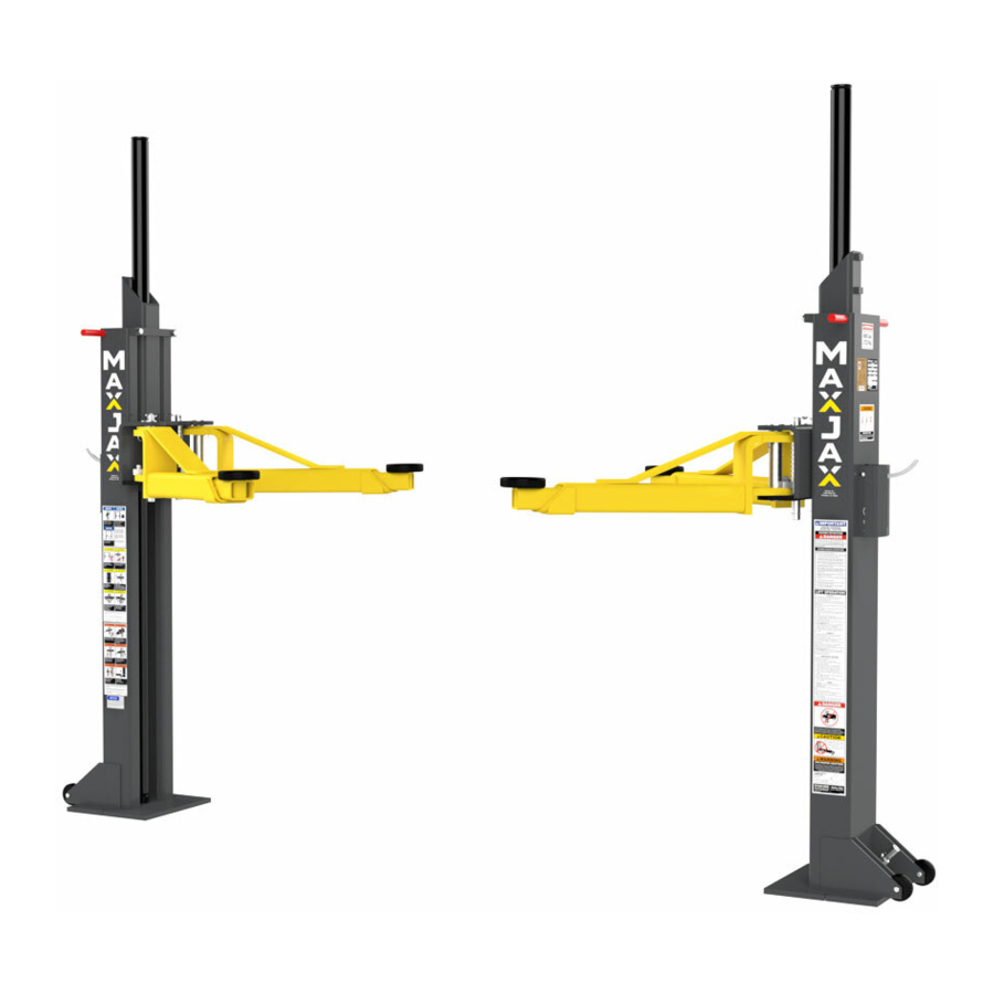
MODEL: M6K
PORTABLE MID-RISE LIFT
6,000 POUND CAPACITY
Patent No. US 8.256.577 B2
Patent No. US 9.150.395.B2
August 2020
P/N# 5900228
requirments for installation and service of
PLEASE READ THE ENTIRE CONTENTS OF THIS MANUAL PRIOR TO INSTALLATION AND OPERATION. BY PROCEEDING WITH LIFT
INSTALLATION AND OPERATION YOU AGREE THAT YOU FULLY UNDERSTAND AND COMPREHEND THE FULL CONTENTS OF THIS
MANUAL. FORWARD THIS MANUAL TO ALL OPERATORS. FAILURE TO OPERATE THIS EQUIPMENT AS DIRECTED MAY CAUSE
INJURY OR DEATH.
Reference ANSI/ALI ALIOM safety
automotive lifts before installing lift.
1
Advertisement
Table of Contents

Related Manuals for MaxJax M6K


Summary of Contents for MaxJax M6K
- Page 1 MaxJax™ 5240 Willis Road Theodore, AL 36582 844-629-5291 M6K USER MANUAL MODEL: M6K PORTABLE MID-RISE LIFT 6,000 POUND CAPACITY Patent No. US 8.256.577 B2 Patent No. US 9.150.395.B2 August 2020 P/N# 5900228 Reference ANSI/ALI ALIOM safety requirments for installation and service of automotive lifts before installing lift.
-
Page 2: Important Notice
IMPORTANT NOTICE 1. Read this manual thoroughly before installing, operating, or maintaining this lift. 2. This lift is designed for indoor use only, and should not be installed in a pit or depression. 3. The floor on which the lift is to be installed must be 4" (101mm) minimum thickness concrete, with a minimum compressive strength of 3000 psi (20 MPa) and reinforced with steel bar. -
Page 3: Important Safety Instructions
IMPORTANT SAFETY INSTRUCTIONS READ THESE SAFETY INSTRUCTIONS ENTIRELY Do not attempt to install this lift if you have never been trained on basic automotive lift installation procedures. Never attempt to lift components without proper lifting tools such as a forklift or crane. Stay clear of any moving parts that can fall and cause injury. - Page 4 21. ONLY TRAINED OPERATORS should operate this lift. All non trained personnel should be kept away from work area. Never let non trained personnel come in contact with, or operate lift. 22. USE LIFT CORRECTLY. Use lift in the proper manner. Never use lifting adapters other than what is approved by the manufacturer.
-
Page 5: Owner / Employer Responsibilities
SAVE THESE INSTRUCTIONS OWNER / EMPLOYER RESPONSIBILITIES • Shall ensure that lift operators are qualified and that they are trained in the safe use and operation of the lift using the manufacturer’s operating instructions and regional requirements. • Shall establish procedures to periodically inspect the lift in accordance with the lift manufacturer’s instructions and regional requirements. -
Page 6: Installer / Operator Protective Equipment
Please read entire manual prior to installation. Do not operate this machine until you read and understand all the dangers, warnings and cautions in this manual. For additional copies or further information, contact: MaxJax™ 5240 Willis Road Theodore, AL 36582... - Page 7 LABEL; ALI/ALCTV-2017 GOLD LABEL, CAN-US; MET LABS MAXJAX POWER UNIT STAND ASSEMBLY ITEM No. PART NUMBER DESCRIPTION 5601535 MAXJAX BOTTOM PLATE WELDMENT, STAND 5601474 M6K HOSE STORAGE BOX WELDMENT 5755171 MAXJAX STAND HANDLE 5737162 MAXJAX STAND SUPPORT PLATE 5215970 MAXJAX HAND CART WHEEL ASSEMBLY 5715041 MAXJAX Ø25 VINYL GRIP...
- Page 8 ITEM No. PART NUMBER DESCRIPTION 5174046 PARTS BAG 5715003 POWER UNIT VIBRATION DAMPENER 5601488 M6K LIFT HEAD PIN WELDMENT 5575061 M6K POST WHEEL 5601487 M6K POST STRAP ASSEMBLY 5736604 TWO POST LIGHT DUTY BOLT ON ARM RESTRAINT GEAR 5210236 MAXJAX SAFETY WELDMENT...
- Page 9 MAXJAX PARTS BAG MAXJAX PARTS BOX...
-
Page 10: Step 1 Selecting Site
INSTALLATION INSTRUCTIONS TOOLS REQUIRED • Hex Key / Metric Allen Wrench Set • Rotary Hammer Drill or Similar • Large Crescent Wrench • 7/8" (22mm) Masonry Bit • Large Phillips Screwdriver • Hammer • 4 Foot Level (1.5 M) • Chalk Line •... -
Page 11: Step 3 Installing Hydraulic Cylinders
STEP 3 INSTALLING HYDRAULIC CYLINDERS Install the column wheels using M8x55 hex head bolts and M8 nylon lock nut (P/N 5575061) (P/N 5530377) onto each column. Turn the columns over and lay them down with the open side up. Slide the lift head (P/N 5535001) to the top of the post. - Page 12 Assemble cart as shown in the figures below: 1. After installing the cart wheels, attach the power unit and rubber Power Unit Dampener pad to the power unit cart using the (4) M8x20 mm Hex Bolts and Nylon lock nuts. (See figure 6) 2.
-
Page 13: Step 5 Site Layout
STEP 5 SITE LAYOUT 1. Determine the location of where the lift will be installed based on the size of vehicles servicing. The dimensions shown below are rough guidelines. "Dry-fit" the vehicles intended to be serviced in the bay by referring to the ALI Lifting Point Guide for appropriate lift points before finalizing the column spacing. -
Page 14: Step 6 Installation Of Power Drop Anchors
STEP 6 INSTALLATION OF POWER DROP ANCHORS 1. Before proceeding, double check location and measurements, make Fig. 10 certain that the base plates of each column are aligned with the chalk/ crayon lines. The concrete must be minimum of 4" (101mm) thick with minimum compressive strength of 3000 psi (20 MPa). - Page 15 7. Install both columns with bolts and washers to anchors, check plumb and measurements as shown below. 8. If shimming is required, insert the shims as necessary under the Fig. 15 base plate so that when the provided 5/8 x 2" anchor bolts are tightened, the columns will be plumb both side to side and front to rear.
-
Page 16: Step 7 Connecting Hydraulic Lines
STEP 7 CONNECTING HYDRAULIC LINES 1. Thread one end of the 3/8 NPT hose fittings into one of the top ports of the Flow Divider. Do this with both hoses. (See figure 16) 3/8 NPTF Hose Fig. 16 Install the Female Quick Disconnect fittings to the opposite end of Fittings each hose. -
Page 17: Step 9 Installing The Lift Arms
STEP 9 INSTALLING THE LIFT ARMS 1. Place the lift arm assembly on the lift heads. Install the lift head pins into the lift head and through the holes in the arm assembly. Install the quick release pin into place on the arm pin. (See figure 20 and 21) Quick Release Pin Fig. -
Page 18: Step 10 Installing The Safety Release Latch
STEP 10 INSTALLING THE SAFETY RELEASE LATCH SEE PAGE 30 STEP 11 BLEEDING THE CYLINDERS With the lift in an elevated position, the hoses connected and the oil reservoir full, loosen the bleeder screws located at the top of each hydraulic cylinder using an allen wrench. Do not completely remove the bleeder screws. Watch and listen for trapped air escape the cylinders and fluid begins to weep from the screw area. -
Page 19: Post Installation Check Off
POST INSTALLATION CHECK OFF Columns are properly leveled Check for overhead obstructions Anchor bolts are tightened Lift arms are level Electric power supply confirmed Arm restraints properly adjusted Check for hydraulic leaks All screws, bolts, and pins are secured Check oil level Surrounding area is clear Lubrication of critical components Operation, maintenance and safety manuals on site... -
Page 20: Step 13 Lift Operation
STEP 13 LIFT OPERATION BE SURE TO READ ALL SAFETY TIPS PRIOR TO OPERATING LIFT. FAILURE TO DO SO MAY RESULT IN SERIOUS INJURY OR DEATH. TO RAISE VEHICLE: 1. Center the vehicle between columns. Adjust vehicle front-to-back so the center of gravity falls in the middle of the columns. -
Page 21: Step 14 Lift Removal
STEP 14 LIFT REMOVAL 1. Depress the lowering valve on the power unit. 2. Ensure that the lift is lowered all the way to the ground and hydraulic pressure is relieved. 3. Disconnect the power unit from the power source and / or ensure that the power to the circuit is shut off to prevent accidental powering on of the lift while disassembling. -
Page 22: Troubleshooting Guide
TROUBLESHOOTING GUIDE BE SAFE: DO NOT OPERATE OR REPAIR EQUIPMENT WITHOUT READING THIS MANUAL AND THE IMPORTANT SAFETY INSTRUCTIONS. KEEP THIS OPERATION MANUAL NEAR THE LIFT AT ALL TIMES. MAKE SURE THAT ALL USERS READ AND UNDERSTAND THIS MANUAL. LIFT WILL NOT RAISE (BUT MOTOR RUNS) POSSIBLE CAUSE 1. -
Page 23: Motor Will Not Run
MOTOR WILL NOT RUN POSSIBLE CAUSE 1. Panel circuit breaker flipped, (5,2,1,3,4) 2. Motor burned out, (1,2,3,6,4) 3. Voltage to motor incorrect, (2,1) 4. CE USERS ONLY: Internal motor circuit breaker flipped (7) 5. CE USERS ONLY: Fuse protecting contractor has blown (8) REMEDY INSTRUCTIONS 1. - Page 24 WILL NOT RAISE ONLY UNDER LOADED CONDITION POSSIBLE CAUSE 1. Air in oil, (4,1,2,3) 2. Cylinder / lift head binding, (5) 3. Cylinder leaks internally, (5) 4. Lift overloaded, (6,5) 5. Lowering valve leaks, (7,1,8,5,9) 6. Motor runs backwards, (10,12,9) 7.
-
Page 29: Technical Service Bulletin
Theodore, AL USA Tel: (844) 629-5291 maxjax.com ECHNICAL ERVICE ULLETIN : MAXJAX M6 AND M6K ODELS UBJECT YDRAULIC EPLACEMENT The purpose of this Technical Service Bulletin is to describe the new Short Hydraulic Hose used for connecting the Power Unit to the Hydraulic Flow Divider. - Page 30 Safety 1. Install the Safety Latch Release on the Safety Weldment Pin. Latch 2. Slide the Retaining Ring on to the Safety Weldment Pin. Release Safety 3. Slide the Safety Release Assembly onto the Safety Weldment Release Plate on the Post. 4.
- Page 31 844-629-5291...
- Page 32 844-629-5291...
Need help?
Do you have a question about the M6K and is the answer not in the manual?
Questions and answers