Advertisement
Quick Links
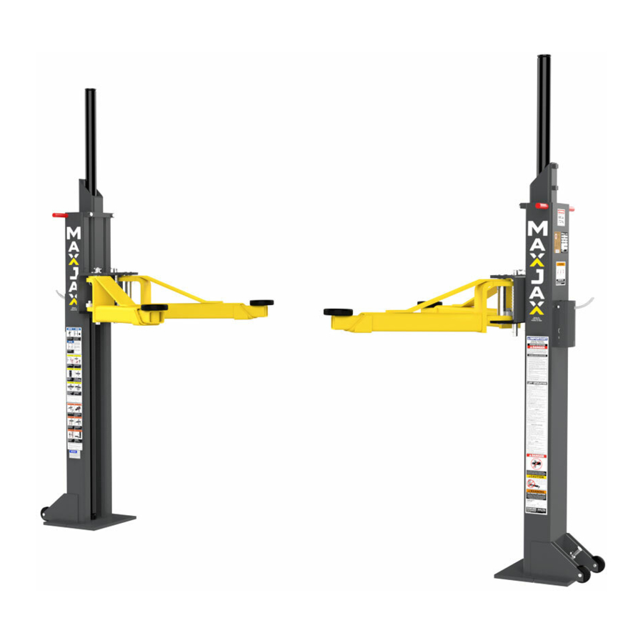
MaxJax™
5240 Willis Road
Theodore, AL 36582
844-629-5291
M6K USER MANUAL
MODEL: M6K
PORTABLE MID-RISE LIFT
6,000 POUND CAPACITY
Patent No. US 8.256.577 B2
Patent No. US 9.150.395.B2
Rev B - February 2021
P/N# 5900228
requirements for installation and service of
PLEASE READ THE ENTIRE CONTENTS OF THIS MANUAL PRIOR TO INSTALLATION AND OPERATION. BY PROCEEDING WITH LIFT
INSTALLATION AND OPERATION YOU AGREE THAT YOU FULLY UNDERSTAND AND COMPREHEND THE FULL CONTENTS OF THIS
MANUAL. FORWARD THIS MANUAL TO ALL OPERATORS. FAILURE TO OPERATE THIS EQUIPMENT AS DIRECTED MAY CAUSE
INJURY OR DEATH.
Reference ANSI/ALI ALIOM safety
automotive lifts before installing lift.
1
Advertisement

Related Manuals for MaxJax M6K


Summary of Contents for MaxJax M6K
- Page 1 MaxJax™ 5240 Willis Road Theodore, AL 36582 844-629-5291 M6K USER MANUAL MODEL: M6K PORTABLE MID-RISE LIFT 6,000 POUND CAPACITY Patent No. US 8.256.577 B2 Patent No. US 9.150.395.B2 Rev B - February 2021 P/N# 5900228 Reference ANSI/ALI ALIOM safety requirements for installation and service of automotive lifts before installing lift.
- Page 2 IMPORTANT NOTICE 1. Read this manual thoroughly before installing, operating, or maintaining this Lift. 2. This Lift is designed for indoor use only, and should not be installed in a pit or depression. 3. The floor on which the Lift is to be installed must be 4" (101mm) minimum thickness concrete, with a minimum compressive strength of 3,000 psi (20 MPa) and reinforced with steel bar.
- Page 3 IMPORTANT SAFETY INSTRUCTIONS READ THESE SAFETY INSTRUCTIONS ENTIRELY Do not attempt to install this lift if you have never been trained on basic automotive lift installation procedures. Never attempt to lift components without proper lifting tools such as a forklift or crane. Stay clear of any moving parts that can fall and cause injury.
- Page 4 21. ONLY TRAINED OPERATORS should operate this lift. All non trained personnel should be kept away from work area. Never let untrained personnel come in contact with, or operate lift. 22. USE LIFT CORRECTLY. Use lift in the proper manner. Never use lifting adapters other than what is approved by the manufacturer.
- Page 5 • • I understand that MaxJax is designed to be installed in indoor locations only. Failure to follow instructions may lead to serious personal injury or death to operator or bystander or damage to property or Lift.
- Page 6 Please read entire manual prior to installation. Do not operate this machine until you read and understand all the dangers, warnings and cautions in this manual. For additional copies or further information, contact: MaxJax™ 5240 Willis Road Theodore, AL 36582...
- Page 7 INSTALLATION INSTRUCTIONS TOOLS REQUIRED • Hex Key / Metric Allen Wrench Set • Rotary Hammer Drill or Similar • 7/8" (22mm) Masonry Bit • Large Crescent Wrench • Large Phillips Screwdriver • Hammer • 4 Foot Level (1.5 M) • Chalk Line •...
- Page 8 STEP 3 INSTALLING THE HYDRAULIC CYLINDERS Install the Post Wheels using M8x55 Hex Head Bolts (P/N 5575061) Fig. 1 and M8 Nylon Nuts onto each Post. (P/N 5530377) (P/N 5535001) P/N 5575061 (See Figure 1) Turn the Posts over and lay them down with the open side up. Slide the Lift Head to the top of the Post.
- Page 9 STEP 4 MOUNTING THE HYDRAULIC POWER UNIT 1. Assemble the Cart as shown. (See Figure 7) Fig. 7 2. Attach the Power Unit and Hydraulic Flow Divider to the P/N 5601474 P/N 5535357 Power Unit Cart using 8 Hex Head Bolts (P/N 5530304) .
- Page 10 IMPORTANT FLOW DIVIDER INFORMATION There is a Hydraulic OUT Port on either side of the Flow Divider, and a Hydraulic IN Port on the lower Ports. Depending on the Flow Divider that came with your Lift, the Ports may be configured differently. Your Lift will not work right if the Flow Divider is installed incorrectly! If your Flow Divider looks like the graphic below, connect the two Long Hydraulic Hoses to the top OUT Ports, and the Short Hydraulic Hose connects to the Bottom Left IN Port.
- Page 11 STEP 5 SITE LAYOUT 1. Determine the location of where the lift will be installed based on the size of vehicles servicing. The dimensions shown below are rough guidelines. "Dry-fit" the vehicles intended to be serviced in the bay by referring to the ALI Lifting Point Guide for appropriate lift points before finalizing the column spacing.
- Page 12 STEP 6 INSTALLING THE ANCHORS Before proceeding, verify location, measurements, and that the Base Plates are aligned with the Chalk Lines (Figure 10). The concrete must be minimum of 4" (101mm) thick with a minimum compressive strength of 3000 psi (20 MPa). Follow the procedure exactly for proper fitting and alignment of Anchors.
- Page 13 Fig. 15 7. Install both Posts with Bolts and Washers to Anchors, check plumb and measurements as shown below. 8. If shimming is required, insert the shims as necessary under the base plate so that when the provided 5/8 x 2" Anchor Bolts are tightened, the Posts will be plumb both side to side and front to rear.
- Page 14 STEP 7 CONNECTING THE HYDRAULIC HOSES 1. Thread one end of the 3/8 NPT Hose Fittings into one of the Top Out Ports on the Flow Divider. Do this with both Hoses. Apply Liquid Thread Sealant to the NPT threaded ends only. (See figure 16). Install the Female Quick Disconnect fittings to the opposite end of each Hose.
- Page 15 STEP 9 INSTALLING THE LIFT ARMS 1. Place the Lift Arm Assembly on the Lift Heads. Install the Lift Head Pins into the Lift Head and through the holes in the Arm Assembly. Install the Quick Release Pin into place on the Arm Pin. (See figure 20 and 21) Fig.
- Page 16 STEP 10 INSTALLING THE SAFETY RELEASE ASSEMBLIES Safety Release Handle (P/N 5737159) 1. Install the Safety Release Handle on the Safety Weldment Pin. 2. Slide the Safety Release Assembly onto the Safety Release Plate on the Post. 3. Insert the Clevis Pin through the Torsion Spring. 4.
- Page 17 STEP 11 BLEEDING THE CYLINDERS Perform the following procedure with no weight on the Lift. The Lift should be fully lowered before proceeding. Carefully check around and under the Lift for any obstructions. Clear any obstructions before proceeding. Connect the Hydraulic Hoses and make sure the Hydraulic Fluid Reservoir is full. Loosen, but do not remove, the bleeder screws on the top of each Hydraulic Cylinder using a hex wrench.
- Page 18 POST INSTALLATION CHECK OFF Columns are properly leveled Check for overhead obstructions Anchor bolts are tightened Lift arms are level Electric power supply confirmed Arm restraints properly adjusted Check for hydraulic leaks All screws, bolts, and pins are secured Check oil level Surrounding area is clear Lubrication of critical components Operation, maintenance and safety manuals on site...
- Page 19 STEP 13 LIFT OPERATION BE SURE TO READ ALL SAFETY TIPS PRIOR TO OPERATING LIFT. FAILURE TO DO SO MAY RESULT IN SERIOUS INJURY OR DEATH. TO RAISE A VEHICLE: 1. Center the Vehicle between Posts. Adjust Vehicle front-to-back so the center of gravity falls in the middle of the Posts.
- Page 20 STEP 14 LIFT REMOVAL 1. Press and hold the Lowering Handle on the Power Unit. 2. Ensure that the Lift is lowered all the way to the ground and hydraulic pressure is relieved. 3. Disconnect the Power Unit from the power source and / or ensure that the power to the circuit is shut off to prevent accidental powering on of the Lift while disassembling.
- Page 21 Lift is making odd noises when in use. Lubricate hinge points using white lithium grease. If you continue to have problems with your Lift, take it out of service, then contact your dealer, visit maxjax.com/support, via email support@maxjax.com, or call (844) 629-5291.
- Page 31 844-629-5291...
- Page 32 FOR PARTS OR TECHNICAL SUPPORT: 1645 Lemonwood Dr. • Santa Paula, CA, 93060 USA 1 (877) 437-6627 844-629-5291 Toll Free: (877) 432-6627...
Need help?
Do you have a question about the M6K and is the answer not in the manual?
Questions and answers