Table of Contents
Advertisement
Available languages
Available languages
Quick Links
Advertisement
Table of Contents

Related Manuals for INNOLIVING INN-520


Summary of Contents for INNOLIVING INN-520
- Page 1 CONDIZIONATORE D’ARIA LOCALE 7000 BTU/H INN-520 MANUALE D’USO USER MANUAL...
-
Page 2: Importanti Norme Di Sicurezza
CONDIZIONATORE D’ARIA Grazie per aver acquistato il condizionatore d’aria locale Innoliving INN-520. PRIMA DELL’USO LEGGERE ATTENTAMENTE IL SEGUENTE MANUALE DI ISTRUZIONI E CONSERVARLO PER FUTURE CONSULTAZIONI. Prima di utilizzare l’apparecchio, leggere attentamente le istruzioni per l’uso e in particolare le avvertenze sulla sicurezza, attenendosi ad esse. Conservare il presente manuale, per l’intera vita utile dell’apparecchio, a scopo di consultazione. - Page 3 essere eseguite dai bambini, a meno che non abbiano un’età superiore agli 8 anni e operino sotto sorveglianza. Tenere l’apparecchio ed il suo cavo fuori dalla portata dei bambini con età inferiore agli 8 anni. • Assicurarsi che i bambini non giochino con l’apparecchio. •...
- Page 4 • Prestare attenzione durante l’utilizzo del prodotto a causa della possibile emissione di vapore caldo. • L’apparecchio non deve essere posto immediatamente sotto a una presa di rete. • Il prodotto deve essere assemblato prima di essere collegato alla tensione di rete. •...
- Page 5 una perdita di propano. • Non far rientrare nessuna persona nella stanza fino all’arrivo del tecnico dell’assistenza qualificato e attendere fino a che tale tecnico non abbia avvisato che è sicuro tornare nella stanza. • Non utilizzare fiamme libere, sigarette o altre possibili fonti di ignizione all’interno o nelle vicinanze del dispositivo.
- Page 6 4) Controllo della presenza di refrigerante L’area deve essere controllata con un rilevatore di refrigerante appropriato prima e durante il lavoro, per garantire che il tecnico sia a conoscenza di atmosfere potenzialmente infiammabili. Accertarsi che il rilevatore di perdite utilizzato sia idoneo all’uso con refrigeranti infiammabili, ad esempio non scintillanti, adeguatamente sigillati o intrinsecamente sicuri.
- Page 7 e alle specifiche corrette. In ogni momento devono essere seguite le linee guida di manutenzione e assistenza del produttore. In caso di dubbi consultare l’assistenza tecnica di un centro qualificato. I seguenti controlli devono essere applicati agli impianti che utilizzano refrigeranti infiammabili: la dimensione della carica è conforme alle dimensioni della stanza in cui sono installate le parti contenenti refrigerante;...
- Page 8 qualsiasi elemento sigillato. Se dovesse essere assolutamente necessario avere un’alimentazione elettrica dell’apparecchiatura durante la manutenzione, allora è necessario disporre di un rilevatore di perdite costantemente in funzione, localizzando quindi quali siano i punti potenzialmente più pericolosi. 2) Quando si lavora su componenti elettrici, prestare particolare attenzione a quanto segue per garantire che il rivestimento non venga alterato in modo tale da influire sul livello di protezione.
- Page 9 5. RILEVAZIONE DI REFRIGERANTI INFIAMMABILI In nessuna circostanza si devono utilizzare potenziali fonti di ignizione nella ricerca o nel rilevamento di perdite di refrigerante. Non utilizzare una torcia ad alogenuri (o qualsiasi altro rilevatore che utilizzi una fiamma nuda). 6. METODI DI RILEVAZIONE DELLE PERDITE I seguenti metodi di rilevazione delle perdite sono considerati accettabili per i sistemi contenenti refrigeranti infiammabili.
- Page 10 del refrigerante deve essere recuperata nei cilindri di recupero corretti. Il sistema deve essere “lavato” con OFN per rendere l’unità sicura. Potrebbe essere necessario ripetere questa procedura più volte. Aria compressa o ossigeno non devono essere utilizzati per questo compito. La pulizia si ottiene interrompendo la condizione di vuoto nel sistema con OFN e continuando a riempire sino a che non si raggiunge la pressione di esercizio, creando uno sfogo verso l’atmosfera e, infine, ricreando la condizione di vuoto.
- Page 11 tutti i refrigeranti vengano recuperati in modo sicuro. Prima di eseguire il lavoro, è necessario prelevare un campione di olio e refrigerante nel caso sia necessaria un’analisi prima di riutilizzare il refrigerante rigenerato. È essenziale che l’energia elettrica sia disponibile prima dell’inizio dell’attività. a) Acquisire familiarità...
- Page 12 11. DISMISSIONE Quando si rimuove il refrigerante da un sistema, per la manutenzione o la dismissione, si consiglia di utilizzare tutti i refrigeranti in modo sicuro. Quando si trasferisce il refrigerante nei cilindri, assicurarsi che vengano utilizzati solo cilindri di recupero del refrigerante appropriati.
-
Page 13: Panoramica Del Prodotto
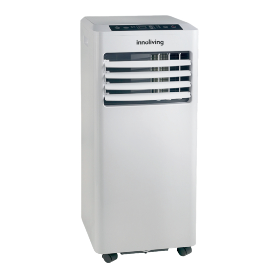
2. PANORAMICA DEL PRODOTTO 2.1 SCHEMA DEL PRODOTTO 1. Pannello di controllo 2. Alette per uscita dell’aria 3. Entrata aria e filtro 4. Cavo di alimentazione 5. Maniglia 6. Scarico dell’aria 7. Foro per il drenaggio con tappo di protezione Nota: l’immagine è... -
Page 14: Installazione
• Telecomando. • Ventola con 2 velocità. • Ruote per una movimentazione agevolata 3. INSTALLAZIONE 3.1 CONTENUTO DELLA CONFEZIONE Aprire la scatola ed estrarre il dispositivo e gli accessori. Estrarre il dispositivo e controllare eventuali danni o graffi su di esso. Accessori: 1. - Page 15 - Polvere eccessiva; - Mancanza di ventilazione, come armadi o librerie; - Superficie irregolare. 3.3 MONTARE IL TUBO DI SCARICO Il condizionatore d’aria deve essere collegato all’esterno in modo che l’aria di scarico possa fuoriuscire dalla stanza (l’aria che fuoriesce dall’apparecchio contiene calore e umidità di scarto). Non sostituire o fare prolunghe al tubo di scarico, altrimenti si avrà...
-
Page 16: Funzionamento
Passaggio 5: collegare il connettore del tubo all’uscita dell’aria di scarico del dispositivo. Passaggio 6: regolare la lunghezza del tubo di scarico flessibile ed evitare pieghe nel tubo. Quindi posizionare il condizionatore vicino a una presa elettrica e collegarlo alla presa. Passaggio 7: regolare le alette di uscita dell’aria e accendere il dispositivo. - Page 17 Power Premere per accendere o spegnere il condizionatore. Selettore Premere per cambiare la modalità di funzionamento tra raffred- Modalità damento, deumidificazione e ventilazione. Spia Indica quale modalità è in funzione tra COOL (Raffreddamento), Modalità DRY (Deumidificazione) e FAN (Ventilazione). Giù Per diminuire la temperatura (16°C~32°C) o impostare il timer.
-
Page 18: Modalità Di Funzionamento
5.2 MODALITÀ DI FUNZIONAMENTO Il condizionatore ha quattro modalità di funzionamento: COOL, FAN, DRY, SLEEP. A. COOL Selezionare questa modalità per raffreddare e abbassare la temperatura nella stanza. - Premere il pulsante MODE sul pannello fino a quando si accende la spia COOL. - Premere il pulsante UP/DOWN per regolare la temperatura visualizzata sullo schermo. - Page 19 inferiore ai 19°C, dopo 20 minuti di funzionamento del condizionatore, verrà avviato lo sbrinamento per 5 minuti e l’indicatore di accensione lampeggerà. 5.5 PROTEZIONE DA SOVRACCARICO In caso di mancanza di alimentazione, per proteggere la macchina è previsto uno stop di 3 minuti prima del riavvio. 6.
-
Page 20: Pulizia E Cura
7. PULIZIA E CURA 7.1. PULIZIA FILTRO ARIA (ogni due settimane) La polvere si accumula sul filtro e limita il flusso d’aria. Il flusso d’aria limitato riduce l’efficienza del sistema e se si blocca può causare danni all’unità. Il filtro dell’aria richiede una pulizia regolare. Il filtro dell’aria è rimovibile per una facile pulizia. Non utilizzare l’unità... -
Page 21: Risoluzione Dei Problemi
8. RISOLUZIONE DEI PROBLEMI Problema Causa Soluzione Controllare il collegamento all’alimentazione. Inserire correttamente il cavo di alimentazione nella presa a muro. Il condizionatore Controllare che l’indicatore del livello dell’ac- Svuotare la bacinella di raccolta rimuovendo il tappo non funziona. qua si accenda di gomma. - Page 22 9. CONSERVAZIONE Se non si utilizza l’unità per un lungo periodo di tempo è consigliato pulire l’unità e asciugarla completamente. Si prega di conservare l’unità attenendosi ai seguenti passaggi: 1. Scollegare l’unità e rimuovere il tubo di scarico e il kit per finestre. 2.
- Page 23 Questo prodotto è conforme a tutte le direttive europee applicabili. Leggere attentamente le istruzioni per l’uso INFORMAZIONI AGLI UTENTI ai sensi del Decreto Legislativo N° 49 del 14 Marzo 2014 “Attuazione della Direttiva 2012/19/UE sui rifiuti di apparecchiature elettriche ed elettroniche (RAEE)” Il simbolo del cassonetto barrato riportato sull’apparecchiatura indica che il prodotto alla fine della propria vita utile deve essere raccolto separatamente dagli altri rifiuti.
-
Page 24: Important Safety Rules
LOCAL AIR CONDITIONER Thank you for purchasing the Innoliving INN-520 local air conditioner. BEFORE USE, CAREFULLY READ THE FOLLOWING INSTRUCTION MANUAL AND KEEP IT FOR FUTURE CONSULTATION. Before using the appliance, carefully read the instructions for use and in particular the safety warnings, following them. - Page 25 • Remove the plug from the socket, you must always pull by the plug and never by the cable. • Do not touch the plug and the device with wet hands. • Remove the plug from the mains when the appliance is not in use. •...
- Page 26 Our powerful portable air conditioners are an excellent cooling solution for rooms, creating a comfortable atmosphere. It also has a ventilation and dehumidification function. They are autonomous systems that do not require any permanent installation, allowing the user to move it to the space where it is most needed. They are commonly used in kitchens, hospitality establishments, computer rooms, garages and many other places where the installation of the outdoor unit of an air conditioner is limited.
- Page 27 1. SAFETY PRECAUTIONS ON MAINTENANCE Please follow these warnings to perform the following operations when servicing an appliance that uses R-290 gas. 1) Check the area Before starting to work on systems containing flammable refrigerants, safety checks are required to ensure that the risk of ignition is minimized. When repairing the refrigeration system, before performing piping work on the system, take the following precautions.
- Page 28 sources of ignition, including cigarette smoke, should be kept sufficiently far from the place of installation, repair, removal and disposal, during which flammable refrigerant can be released into the surrounding space. Before starting work, the area around the equipment should be inspected to ensure that there are no flammable hazards or ignition hazards.
-
Page 29: Repairs To Sealed Components
the operation, a suitable interim solution must be used. This must be reported to the owner of the equipment, so all parties are advised. Initial safety checks must include: that the capacitors are discharged: this must be done safely to avoid the possibility of sparks;... -
Page 30: Detection Of Flammable Refrigerants
atmosphere. The test apparatus must have correct nominal values. Replace components only with parts specified by the manufacturer. Other parts can cause the refrigerant to ignite in the atmosphere from a leak. 4. WIRING Verify that the wiring is not subject to wear, corrosion, excessive pressure, vibration, sharp edges, or other adverse environmental effects. -
Page 31: Removal And Evacuation
7. REMOVAL AND EVACUATION When you want to intervene on the refrigerant circuit to carry out a repair - or for any other purpose - conventional procedures must be used. However, it is important to follow some of the best practices since flammability is a risky and important eventuality. - Page 32 Before leaving the work area, a tightness check must be carried out. 9. DECOMMISSIONING OF THE REFRIGERANT Before performing this procedure, it is essential that the technician is familiar with the equipment and all its details. It is good practice to recommend that all refrigerants are safely recovered.
- Page 33 drained of refrigerant. The label must be dated and signed. Make sure there are labels on the equipment indicating that the equipment contains flammable refrigerant. 11. DISPOSAL When removing refrigerant from a system, for maintenance or decommissioning, it is recommended that all refrigerants be used safely. When transferring refrigerant to cylinders, ensure that only appropriate refrigerant recovery cylinders are used.
-
Page 34: Product Overview
2. PRODUCT OVERVIEW 2.1 PRODUCT PARTS 1. Control panel 2. Air outlet wings 3. Air inlet and filter 4. Supply cable 5. Handle 6. Air outlet 7. Drainage hole with protection cap Note: the image is for reference only. Please refer to the actual product for detailed information. 2.2 FEATURES - High cooling efficiency in a compact size. -
Page 35: Installation
- Automatic defrost function at low ambient temperatures. - Remote control. - Fan with 2 speeds. - Wheels for easy transport. 3. INSTALLATION 3.1 CONTENTS OF THE PACKAGE Open the box and take out the device and accessories. Take out the device and check for any damage or scratches on it. Accessories: 1. -
Page 36: Connect The Drain Hose
3.3 CONNECT THE DRAIN HOSE The air conditioner must be connected to the outside so that the exhaust air can escape from the room (the air that comes out of the appliance contains waste heat and moisture). Do not replace or make extensions to the exhaust pipe, otherwise there will be a decrease in efficiency and the possibility of switching off the device due to low back pressure. -
Page 37: Control Panel And Display
Step 5: Connect the hose connector to the exhaust air outlet of the device. Step 6: Adjust the length of the flexible drain hose and avoid kinks in the hose. Then place the air conditioner near an electrical outlet. Step 7: Adjust the air outlet flaps and turn on the device. 4. - Page 38 POWER Push to turn the conditioner on or off. MODE Push to change the functioning mode among cooling, dehumidifi- selector cation and ventilation. MODE It shows which mode is working among COOL (cooling), DRY light (dehumidification) and FAN (ventilation). DOWN To reduce the temperature (16°C32°C) or set the timer.
-
Page 39: Mode Of Operation
5.2 MODE OF OPERATION The air conditioner has four operating modes: COOL, FAN, DRY, SLEEP. A. COOL - Select this mode to cool and lower the temperature in the room. - Press the MODE button on the panel until the COOL indicator lights up. - Press the UP / DOWN button to adjust the temperature displayed on the screen. -
Page 40: Overload Protection
5.5 OVERLOAD PROTECTION In the event of a power failure, the machine will be stopped for 3 minutes before restarting to protect it. 6. DRAINAGE Manual drainage 1) When the machine stops after the water tank is filled, disconnect the power plug. Note: Si prega di spostare la macchina con cautela, in modo da non versare l’acqua nella vaschetta nella parte inferiore del dispositivo. -
Page 41: Cleaning And Care
7. CLEANING AND CARE 7.1. AIR FILTER CLEANING (every two weeks) Dust builds up on the filter and restricts the air flow. Restricted airflow reduces the efficiency of the system and if it becomes blocked it can cause damage to the unit. The air filter requires regular cleaning. -
Page 42: Problem Solving
8. PROBLEM SOLVING Problem Cause Solution Check the power connection. Insert correctly the power cable in the main socket. The air condi- Check that the water level indicator lights up. Empty the drain container by removing the rubber tioner doesn’t cap. -
Page 43: Data Label
3. Clean the filter and allow it to dry completely in a shaded area. 4. Collect the power cord. 5. Reinstall the filter in its position. 6. The unit must be kept upright during storage. 7. Store the machine in a ventilated, dry, non-corrosive environment and in a safe indoor place. ATTENTION: When storing the air conditioner in its original box, make sure it is completely dry to prevent damage to components and mold growth. - Page 44 Innoliving Spa Via Merloni, 2/B 60131 Ancona Italy Tel 0712133550 www.innoliving.it MADE IN CHINA...
Need help?
Do you have a question about the INN-520 and is the answer not in the manual?
Questions and answers