Table of Contents
Advertisement
Quick Links
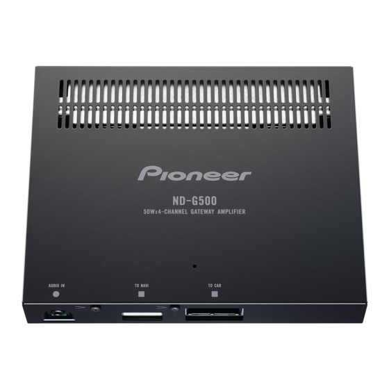
4-CHANNEL GATEWAY AMPLIFIER
ND-G500
For details, refer to "Important Check Points for Good Servicing".
PIONEER CORPORATION
PIONEER ELECTRONICS (USA) INC. P.O. Box 1760, Long Beach, CA 90801-1760, U.S.A.
PIONEER EUROPE NV Haven 1087, Keetberglaan 1, 9120 Melsele, Belgium
PIONEER ELECTRONICS ASIACENTRE PTE. LTD. 253 Alexandra Road, #04-01, Singapore 159936
PIONEER CORPORATION 2008
4-1, Meguro 1-chome, Meguro-ku, Tokyo 153-8654, Japan
ND-G500/XS/E5
/XS/E5
K-ZZZ. APR. 2008 Printed in Japan
ORDER NO.
CRT4156
Advertisement
Table of Contents

Related Manuals for Pioneer ND-G500XS


Summary of Contents for Pioneer ND-G500XS
- Page 1 PIONEER CORPORATION 4-1, Meguro 1-chome, Meguro-ku, Tokyo 153-8654, Japan PIONEER ELECTRONICS (USA) INC. P.O. Box 1760, Long Beach, CA 90801-1760, U.S.A. PIONEER EUROPE NV Haven 1087, Keetberglaan 1, 9120 Melsele, Belgium PIONEER ELECTRONICS ASIACENTRE PTE. LTD. 253 Alexandra Road, #04-01, Singapore 159936 PIONEER CORPORATION 2008 K-ZZZ.
-
Page 2: Safety Information
SAFETY INFORMATION This service manual is intended for qualified service technicians; it is not meant for the casual do-it-yourselfer. Qualified technicians have the necessary test equipment and tools, and have been trained to properly and safely repair complex products such as those covered by this manual. Improperly performed repairs can adversely affect the safety and reliability of the product and may void the warranty. - Page 3 [Important Check Points for Good Servicing] In this manual, procedures that must be performed during repairs are marked with the below symbol. Please be sure to confirm and follow these procedures. 1. Product safety Please conform to product regulations (such as safety and radiation regulations), and maintain a safe servicing environment by following the safety instructions described in this manual.
-
Page 4: Table Of Contents
CONTENTS SAFETY INFORMATION............................. 2 1. SERVICE PRECAUTIONS ..........................5 1.1 SERVICE PRECAUTIONS ........................5 1.2 NOTES ON SOLDERING .......................... 5 2. SPECIFICATIONS ............................6 2.1 SPECIFICATIONS ............................. 6 2.2 CONNECTION DIAGRAM ......................... 7 3. BASIC ITEMS FOR SERVICE.......................... 8 3.1 CHECK POINTS AFTER SERVICING....................... 8 4. -
Page 5: Service Precautions
1. SERVICE PRECAUTIONS 1.1 SERVICE PRECAUTIONS 1. You should conform to the regulations governing the product (safety, radio and noise, and other regulations), and should keep the safety during servicing by following the safety instructions described in this manual. 2. Be careful in handling ICs. Some ICs such as MOS type are so fragile that they can be damaged by electrostatic induction. -
Page 6: Specifications
2. SPECIFICATIONS 2.1 SPECIFICATIONS ND-G500/XS/E5... -
Page 7: Connection Diagram
2.2 CONNECTION DIAGRAM ND-G500/XS/E5... -
Page 8: Basic Items For Service
3. BASIC ITEMS FOR SERVICE 3.1 CHECK POINTS AFTER SERVICING To keep the product quality after servicing, please confirm following check points. r i f Confirm whether the customer complain has The customer complain must not be been solved. reappeared. Audio and operations must be normal. -
Page 9: Block Diagram
4. BLOCK DIAGRAM There is not information to be shown in this chapter. 5. DIAGNOSIS 5.1 TROUBLESHOOTING Output audio from the Speaker is switched by “AMP control terminal” (Blue/white cable) If the terminal signal is “L”, the audio from Mini-plug (AVIC-F500BT) is selected. If the terminal signal is “H”, Car stereo audio is selected. -
Page 10: Disassembly
7. DISASSEMBLY (Caution) 1) Approximately one hour after activating, the temperature on part of outer surface reaches nearly 70 C. Therefore, be careful not to get burn, immediately after turning off power. 2) Watch out for a hot heat sink. Operations while removing a heat sink can cause failure. -
Page 11: Each Setting And Adjustment
8. EACH SETTING AND ADJUSTMENT There is not information to be shown in this chapter. 9. EXPLODED VIEWS AND PARTS LIST OTES : Parts marked by " * " are generally unavailable because they are not in our Master Spare Parts List. The >... -
Page 12: Exterior
9.2 EXTERIOR ND-G500/XS/E5 ND-G500/XS/E5... - Page 13 EXTERIOR SECTION PARTS LIST Mark No. Description Part No. Cord Assy CDP1133 > Fuse(10 A) CEK1136 CNS1472 Resistor RS1/2PMF102J Screw ASZ26P050FTC Screw BSZ26P060FTB Screw BSZ26P160FTC Chassis CNA3074 Case CNB3511 Insulator CNN2375 Heat Sink CNR1962 Plug(CN700) CKM1132 Holder CND4613 Holder CND4614 Holder CND4694 Connector(JA700)
-
Page 14: Schematic Diagram
10. SCHEMATIC DIAGRAM 10.1 AMP UNIT(GUIDE PAGE) Note: When ordering service parts, be sure to refer to " EXPLODED VIEWS AND PARTS LIST" or "ELECTRICAL PARTS LIST". Large size SCH diagram Guide page Detailed page > ND-G500/XS/E5... - Page 15 AMP UNIT CTH1381 NOTE : Symbol indicates a resistor. No differentiation is made between chip resistors and discrete resistors. Symbol indicates a capacitor. No differentiation is made between chip capacitors and discrete capacitors. The > mark found on some component parts indicates the importance of the safety factor of the part.
- Page 16 ND-G500/XS/E5...
- Page 17 ND-G500/XS/E5...
- Page 18 ND-G500/XS/E5...
- Page 19 ND-G500/XS/E5...
-
Page 20: Pcb Connection Diagram
11. PCB CONNECTION DIAGRAM 11.1 AMP UNIT NOTE FOR PCB DIAGRAMS AMP UNIT 1.The parts mounted on this PCB include all necessary parts for several destination. For further information for respective destinations, be sure to check with the schematic dia- gram. - Page 21 SIDE A > FU 770 (A,138,20) Fuse 4 A CEK1260 IC700 C705 Q730 R732 R733 R735 R734 R731 C286 R736 C282 C289 C298 C764 C299 C765 C730 C706 C285 R730 C284 C283 C731 Q733 R303 C725 C320 C763 R312 C287 C288 R313 D320...
- Page 22 AMP UNIT ND-G500/XS/E5...
- Page 23 SIDE B ND-G500/XS/E5...
-
Page 24: Electrical Parts List
12. ELECTRICAL PARTS LIST NOTE: Parts whose parts numbers are omitted are subject to being not supplied. The part numbers shown below indicate chip components. Chip Resistor RS1/_S___J,RS1/__S___J Chip Capacitor (except for CQS..) CKS.., CCS.., CSZS..The > mark found on some component parts indicates the importance of the safety factor of the part. Therefore, when replacing, be sure to use parts of identical designation. - Page 25 Circuit Symbol and No. Part No. Circuit Symbol and No. Part No. R 233 (A,35,26) RS1/10S103J R 841 (A,14,64) RS1/16S473J R 234 (A,36,31) RS1/16S561J R 842 (A,16,61) RS1/16S103J R 240 (A,32,26) RS1/10S103J CAPACITORS R 241 (A,30,26) RS1/10S103J R 242 (A,28,26) RS1/10S103J C 200 (A,61,33)
- Page 26 Circuit Symbol and No. Part No. C 746 (A,51,49) CKSRYB104K16 C 747 (A,47,49) CEHVW220M16 C 749 (A,30,49) CKSRYB104K16 C 750 (A,26,48) CEHVW220M16 C 751 (A,49,73) CCSRCH101J50 C 752 (A,49,72) CKSRYB224K16 C 753 (A,43,72) CEHVW220M16 C 754 (A,26,73) CCSRCH101J50 C 755 (A,26,72) CKSRYB224K16 C 756...
Need help?
Do you have a question about the ND-G500XS and is the answer not in the manual?
Questions and answers