Table of Contents
Advertisement
STEREO AMPLIFIER
Î
STANDBY/ON
STANDBY
POWER
OFF
ON
A
SPEAKERS
B
BASS
PHONES
Thank you for buying this PIONEER product.
Please read through these operating instructions so you will know how to
operate your model properly. After you have finished reading the instruc-
tions, put them away in a safe place for future reference.
In some countries or regions, the shape of the power plug and power
outlet may sometimes differ from that shown in the explanatory draw-
ings. However, the method of connecting and operating the unit is the
same.
WARNING:
TO PREVENT FIRE OR SHOCK HAZARD, DO
NOT EXPOSE THIS APPLIANCE TO RAIN OR MOISTURE.
[For European model]
If the socket outlets on the associated equipment are not suitable for the plug supplied with the product the plug must be removed
and appropriate one fitted.
The cut-off plug must be disposed of as an electrical shock hazard could exist if connected to a socket outlet.
IMPORTANT
The lightning flash with arrowhead symbol, within an
equilateral triangle, is intended to alert the user to the
presence of uninsulated "dangerous voltage" within the
product's enclosure that may be of sufficient magnitude to
constitute a risk of electric shock to persons.
IMPORTANT
FOR USE IN THE UNITED
KINGDOM
The wires in this mains lead are coloured in
accordance with the following code :
Blue
:Neutral
Brown
:Live
If the plug provided is unsuitable for your socket
outlets, the plug must be cut off and a suitable plug
fitted.
z¿.?/B Direct Energy MOS
VOLUME
TREBLE
LOUDNESS
MIN
RISK OF ELECTRIC SHOCK
CAUTION:
TO PREVENT THE RISK OF ELECTRIC SHOCK, DO NOT
REMOVE COVER (OR BACK). NO USER-SERVICEABLE
PARTS INSIDE. REFER SERVICING TO QUALIFIED
SERVICE PERSONNEL.
The cut-off plug should be disposed of and must not be
inserted into any 13 amp socket as this can result in electric
shock. The plug or adaptor or the distribution panel should be
provided with 5 amp fuse. As the colours of the wires in the
mains lead of this appliance may not correspond with coloured
markings identifying the terminals in your plug, proceed as
follows :
The wire which is coloured blue must be connected to the
terminal which is marked with the letter N or coloured black.
The wire which is coloured brown must be connected
to the terminal which is marked with the letter L or coloured
red.
STEREO AMPLIFIER
z¿.?/B
LINE/
CD
TUNER
PHONO
SB
BALANCE
INPUT SELECTOR
DIRECT/
SB MODE
MAX
L
R
This product complies with the Low Voltage Directive (73/23/
EEC), EMC Directives (89/336/EEC, 92/31/EEC) and CE Marking
Directive (93/68/EEC).
CAUTION
DO NOT OPEN
STANDBY / ON
AMP
TAPE
SELECT
TAPE 1/
TAPE 2
CD-R/MD
MONITOR
DECK
4
DISC
SELECT
CD
REC SELECTOR
TAPE 1 TAPE 2
CD
TUNER
STEREO AMPLIFIER
REMOTE CONTROL UNIT
OFF
SOURCE
The exclamation point within an equilateral triangle is intended
to alert the user to the presence of important operating and
maintenance (servicing) instructions in the literature
accompanying the appliance.
Do not connect either wire to the earth terminal of a
three pin plug.
NOTE
After replacing or changing a fuse, the fuse cover in the
plug must be replaced with a fuse cover which corre-
sponds to the colour of the insert in the base of the plug
or the word that is embossed on the base of the plug, and
the appliance must not be used without a fuse cover. If
lost, replacement fuse covers can be obtained from your
dealer.
Only 5 A fuses approved by B.S.I. or A.S.T.A. to B.S.
1362 should be used.
CD
TUNER
TAPE
2
7
3
1
TAPE
¡
I
DECK
II
¢
7
3
CD
_
+
STATION
TUNER
+
TUNER PHONO
LINE VOLUME
Î
1
<ARB7238>
Advertisement
Table of Contents

Related Manuals for Pioneer A-509R


Summary of Contents for Pioneer A-509R
- Page 1 PHONES LOUDNESS SB MODE Thank you for buying this PIONEER product. Please read through these operating instructions so you will know how to operate your model properly. After you have finished reading the instruc- tions, put them away in a safe place for future reference.
-
Page 2: Table Of Contents
Check the power cord once in a while. unit for ventilation to improve heat radiation (at least 60 cm at When you find it damaged, ask your nearest PIONEER authorized top, 10 cm at rear, and 30 cm at each side). If not enough space service center or your dealer for a replacement. -
Page 3: Connections
CONNECTIONS Before making or changing the connections, switch off the power switch and disconnect the power cord from the AC outlet. Cassette deck/ Adaptor component Turntable CD recorder/ (graphic equalizer, etc.) Cassette deck/MD recorder MD recorder PLAY PLAY E u r o p e a n ·... -
Page 4: Connecting The Speaker Cords
CONNECTING THE SPEAKER CORDS REMOTE CONTROL CORD CONNECTIONS By interconnecting the CONTROL jacks of Pioneer units with the 1. Strip off the vinyl covering and twist the tip of the wire core. Î mark, the entire system can be operated with this remote... -
Page 5: Panel Facilities
PANEL FACILITIES (REAR PANEL) Illustration shows U.K. model 2 3 4 5 6 7 89 E u r o p e a n model only AC OUTLET SPEAKERS SIGNAL AC INLET PHONO TUNER LINE/ TAPE1/CD–R/MD TAPE2 MONITOR SURROUND PLAY PLAY BACK SWITCHED 100W MAX... -
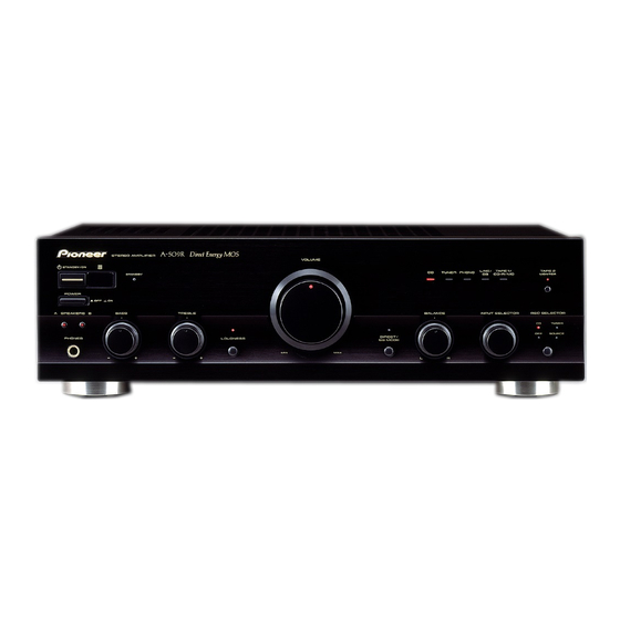
Page 6: Front Panel
PANEL FACILITIES (FRONT PANEL) z¿.?/B Direct Energy MOS STEREO AMPLIFIER VOLUME Î STANDBY/ON TAPE 2 LINE/ TAPE 1/ TUNER PHONO STANDBY CD-R/MD MONITOR POWER SPEAKERS BASS TREBLE BALANCE INPUT SELECTOR REC SELECTOR TUNER SOURCE DIRECT/ LOUDNESS PHONES SB MODE VOLUME indicator POWER ( OFF/ ON) switch... - Page 7 LINE/SURROUND BACK input (the function name is LINE/SB) with a input sensitivity of 1 V. For example, when the set is combined with one of Pioneer’s Surround Back compatible receiver, the set can be used as the Surround Back amplifier.
-
Page 8: Operations
OPERATIONS <To monitor audio> BEFORE BEGINNING OPERATIONS The recorded audio can be monitored only when the REC SE- LECTOR switch is set to [CD] or [TUNER]. 1. Set the VOLUME control to minimum. 1 Set the REC SELECTOR switch to [CD] or [TUNER]. 2. -
Page 9: Remote Control
• The accessory remote control unit can be used to control some functions of other Pioneer cassette decks, CD players and tun- Open the battery compartment cover on the back of the remote ers (only those Pioneer components bearing the Î mark). - Page 10 TAPE 1 : For playback with a cassette deck, CD recorder or When the accessory remote control unit is used to operate MD recorder connected to the TAPE 1/CD-R/MD other PIONEER components with the Î mark, it cannot be terminals. used to operate functions which do not correspond to the TAPE 2 : For playback with a cassette deck or adaptor con- functions listed on the remote control unit.
-
Page 11: Troubleshooting
Sometimes the trouble may lie in another component. Investigate the other components and electrical appli- ances being used. If the trouble cannot be rectified even after exercising the checks listed below, ask your nearest PIONEER authorized service center or your dealer to carry out repair work. -
Page 12: Specifications
PIONEER ELECTRONICS AUSTRALIA PTY. LTD. 178-184 Boundary Road, Braeside, Victoria 3195, Australia TEL: [03] 9586-6300 PIONEER ELECTRONICS DE MEXICO S.A. DE C.V. San Lorenzo Num 1009 3er piso Desp. 302 Col. Del Valle, Mexico D.F. C.P. 03100 TEL: 5-688-52-90 Printed in Japan <ARB7238-A>...
Need help?
Do you have a question about the A-509R and is the answer not in the manual?
Questions and answers