Table of Contents
Advertisement
Quick Links
Advertisement
Table of Contents

Related Manuals for Tri-Clover Tri-Flo CL Series


Summary of Contents for Tri-Clover Tri-Flo CL Series
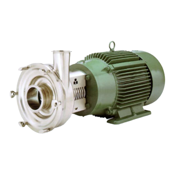
- Page 1 CLSM-98a Tri-Flo CL Series ® Centrifugal Pumps Service & Installation Manual...
-
Page 2: Table Of Contents
CONTENTS Thank you for purchasing a Tri-Clover Product! This manual contains disassembly and assembly instructions, maintenance procedures, troubleshooting, and a complete parts list for all CL Series Centrifugal Pumps designed and manufactured by Tri-Clover Inc., Kenosha, Wisconsin. READ THIS MANUAL carefully to learn how to service these pumps. Failure to do so could result in personal injury or equipment damage. -
Page 3: Safety
DO NOT modify the pump. Modifying the pump creates unsafe conditions and voids all warranties. DO use Tri-Clover spare parts when replacing a component of the pump. DO NOT place the pump in an application where the service ratings are exceeded. -
Page 4: Important Safety Information
SAFETY IMPORTANT SAFETY INFORMATION The following DANGER, WARNING, AND CAUTION signs and their meanings are used within these instructions. DANGER Indicates an imminently hazardous situation which, if not avoided, will result in death or serious injury. The word Danger is used in the most extreme cases. -
Page 5: Technical Information
TECHNICAL INFORMATION TECHNICAL DATA SPECIFICATIONS Maximum Inlet Pressure ................ 145 PSI (1000 kPa) (10 bar) Temperature Range................14 F - 284 F (-10 C to 140 Typical Motor Noise Level ..................... 60 - 80 dB(A) MATERIALS Product Wetted Steel Parts ....................AISI 316L Product Wetted Seals ..................... -
Page 6: Installation
Motor Service/Instruction Manual • Test Certificate certifying the performance of the pump. (if pump is supplied with a motor from Tri-Clover) Remove all packing materials from the pump and motor. Check the suction inlet and discharge outlet for any pieces of packing. -
Page 7: Installation
INSTALLATION INSTALLATION WARNING Only authorized electricians should connect the pump. Ensure sufficient clearance around Mounting surface should be flat and the motor and pump. level. Legs are adjustable. Legs are not available on NEMA 300/IEC200 frames and above. Allow sufficient access for inspection and cleaning. -
Page 8: Operational Check
INSTALLATION OPERATIONAL CHECK WARNING Never run the pump with both the suction side and the pressure side blocked. This will cause serious damage to the pump. WARNING Always check rotation without liquid in the pump. WARNING Do not operate the pump without the seal guard in place. -
Page 9: Maintenance
MAINTENANCE CLEANING AND REPAIR WARNING Do Not touch the pump when running the Clean-In-Place procedure. If the pump is installed in a processing piping system designed for Clean-In-Place (CIP), pump disassembly is not required. A recommended CIP procedure is included in these instructions. If CIP is not available, disassemble the pump according to the disassembly instructions provided. -
Page 10: Maintenance
MAINTENANCE DISASSEMBLY REMOVING PUMP PARTS High voltage. Only an authorized electrician should disconnect the pump. WARNING Relieve pressure and remove all fluid from pump prior to disassembly. Slot 1. Remove seal guard (32) by removing screw (33). 2. Remove wingnuts (6) securing cover (3) to casing (1). 3. - Page 11 MAINTENANCE 22, 28 If disassembling pump with stuffing box and flushing pipes, remove as follows: 1. Remove flushing pipes (24) from stuffing box (22 or 28). 2. Remove casing (1) by removing nuts (13) and washers (14). 3. Remove stuffing box (22 or 28) from casing by removing two screws (23) securing stuffing box to casing.
- Page 12 MAINTENANCE ROTATING SEALS DISASSEMBLY 1. Remove and disassemble seals according to the appropriate configuration shown and described. Type DG - External Balanced Seal 2. Remove the rotating seal (15), o-ring (5), spring (16) and drive collar (17) from stub shaft. CL4311 and CL6410: Remove 15, 5, 16, and 18 from the stub shaft.
- Page 13 MAINTENANCE Type EG - Water Cooled Balanced Double Seal 1. Remove front rotating seal (15), o-ring (5), spacing ring (25) spring (16), o-ring (5), and rear rotating seal (15) from stub shaft. 2. Remove rear stationary seal (26) o-ring (27), and o-ring (20) from stuffing box (28). John Crane Double 8 seal 1.
- Page 14 MAINTENANCE PUMP PARTS DISASSEMBLY After the seals are removed and disassembled, remove the following: Screws are metric. Wrench size is 10mm. 1. Remove pump adapter (29) from motor by removing hex head cap screws (30) and washers (31). 2. Remove compression ring (36), threaded compression ring (35) and retaining ring (40) (used on 1.5 HP and 2 HP motors only) by removing screws (37) and washers (38).
-
Page 15: Inspection
• Inspect impeller for damage from cavitation. Cavitation damage appears as pitting on the impeller surfaces. ASSEMBLY Use only Tri-Clover spare parts when replacing any component of the CL pump. Use of non-Tri-Clover parts could result in pump damage or malfunction. - Page 16 MAINTENANCE 4. Place stub shaft with parts assembled on motor shaft. 5. Stub shaft should be placed so after the pump adapter is installed, the distance between the end of the stub shaft and the motor flange on the pump adapter is between ”...
- Page 17 MAINTENANCE 2. Remove impeller. 3. Remove casing (1) by removing nuts (13) and washers (14). 4. Torque hex head screws (37) securing the compression ring and threaded compression ring to 132 lb-in or 11 lb-ft (15 Nm). Note that hex head screws are metric (wrench size is 10mm). Torque 6 compression ring screws to 132 lb-in or 11 lb-ft (15Nm).
- Page 18 MAINTENANCE Torque screw to 180 lb-in or 15 ft-lb Torque screw to 72 lb-in (8 Nm). (21 Nm). For the CL4311 and CL6410, For the CL4311 and CL6410, torque torque screws to 60 lb-in (7 Nm). screws to 30 ft-lb (41 Nm). 3.
- Page 19 MAINTENANCE Torque screws to 72 lb-in (8 Nm). For the CL4311 and 6410, torque screws to 60 lb-in (7 Nm). 3. Install front gasket (11), stationary seal (12), rear gasket (11) and seal gland (10) into casing (1) using Allen screws (9) and washers (38). Torque the screws to 72 lb-in (8 Nm).
- Page 20 MAINTENANCE Notch in Cap Drive Collar Pin 9. Install the stainless steel drive collar (18) with the spring (16) and rotating seal (15) onto the stub shaft. Ensure the drive collar pin enters the notch on the rotating seal cup when the spring is compressed.
- Page 21 MAINTENANCE Type EG - Water Cooled Balanced Double Seal Torque screw to 72 lb-in (8 Nm) For the CL4311 and 6410, torque screws to 60 lb-in (7 Nm). 1. Install front gasket (11), stationary seal (12), rear gasket (11) and seal gland (10) into casing (1) using Allen screws (9) and washers (38).
- Page 22 MAINTENANCE 7. Install the other seal cup, with seal attached (15) on the spring. 8. Place the stuffing box (28) over rotating seal assembly, and secure it to the casing using the two screws (23). Note: With the stuffing box secured, reach inside the opening and ensure that the rotating seal assembly is centered in the stuffing box.
- Page 23 MAINTENANCE 14. Install o-ring (5) in impeller. 15. Install impeller screw (4) on stub shaft. Torque impeller screw to 180 lb-in or 15 lb-ft (21 Nm). For the CL4311 and CL6410, torque the impeller screw to 30 lb-ft (41 Nm). 16.
- Page 24 MAINTENANCE 5. Slide casing (1) with the assembled seals onto the stub shaft. Use caution when sliding assembled seals and stuffing box onto stub shaft. 6. Install casing (1) to pump adapter with nuts (13) and washers (14). Tighten nuts and washers. 7.
- Page 25 MAINTENANCE FINAL ASSEMBLY 1. Install 0-ring (8) onto cover (3). 2. Install cover (3) onto casing (1) with wingnuts (6). 3. Install seal guard (32) using screw (33). - 25 -...
-
Page 26: Troubleshooting
The troubleshooting chart applies to problems which may arise during pump operation. The chart assumes that the pump is correctly installed and is the correct size for the application. Contact Tri-Clover if assistance is required. Refer to the motor manufacturer’s operating and maintenance manual for motor troubleshooting information. - Page 27 TROUBLESHOOTING PROBLEM PROBABLE CAUSE REMEDY 5. Pump is noisy. a. Bent impeller. a. Remove cover and check impeller against a known straightedge. b. Motor is rotating in the b. Verify motor is wired wrong direction. according to manufacturer’s instructions. c. Impeller clearance is not c.
-
Page 28: Parts List
2. Pump serial number (located on nameplate). 3. Description and part key number from the parts list. The exploded view and parts key facilitate ordering repair parts from Tri-Clover. All parts for the CL pump are keyed to the parts list. -
Page 29: Exploded View
EXPLODED VIEW PARTS LIST FOR ALL CL SERIES PUMPS See Seal Types Below TYPE DG - EXTERNAL BALANCED SEAL JOHN CRANE DOUBLE 8 SEAL TYPE FG - WATER COOLED SINGLE SEAL TYPE EG - WATER COOLED BALANCED DOUBLE SEAL - 29 -... -
Page 30: Cross Sectional View
Type EG Seal - 2 o-rings bearings. Contact your local Tri-Clover EG Seal requires two Rotating Seals. distributor or Tri-Clover for more information. CL4311 and CL6410 require 8 wing nuts and studs. Required on 1½ and 2 horsepower motors CL4311 and CL6410 require 4 nuts and 4 washers. - Page 31 PARTS LIST See back page for cross sectional drawing. - 31 -...
-
Page 32: Cl Pump Replacement Parts
15 - 28 (Seal Parts) Refer to Seal Replacement Parts later in this manual. * Other port connections available upon request. Contact Tri-Clover for details. ** Cut down impeller sizes available upon request. Contact Tri-Clover for details. - 32 -... -
Page 33: Cl Pump Replacement Parts
9612-7301-01 9612-7307-01 9612-7307-01 9612-7307-01 9612-7307-01 15 - 28 (Seal Parts) Refer to Seal Replacement Parts later in this manual. * Other port connections available upon request. Contact Tri-Clover for details. ** Smaller impeller sizes available upon request. Contact Tri-Clover for details. - 33 -... -
Page 34: Cl Pump Replacement Parts
PARTS LIST Click here to Order Parts CL PUMP REPLACEMENT PARTS 140TC 180TC 210TC 250TC 280TSC 320TSC NEMA NEMA NEMA NEMA NEMA NEMA Frames Frames Frames Frames Frames Frames Description Part Part Part Part Part Part Number Number Number Number Number Number 29 Adapter... -
Page 35: Cl Pump Replacement Parts
PARTS LIST Click here to Order Parts CL PUMP REPLACEMENT PARTS 213-215 TC 254-256 TC 284-286 TC 324-365 TSC 405 TSC Description Part Number Part Number Part Number Part Number Part Number Adapter 9612-7205-03 9612-7205-03 9612-7205-01 9612-7205-02 9612-7205-02 Screw, Motor 189888 189888 189888... -
Page 36: Seal Replacement Parts - Type Dg (External Balanced Seal)
PARTS LIST Click here to Order Parts SEAL REPLACEMENT PARTS - Type DG (External Balanced Seal) CL2264 CL4359 CL2265 CL4378 CL2284 CL4311 CL4387 Description CL3285 CL4488 CL3295 Part Number Part Number Part Number O-Ring - Buna N 9612-7301-01 9612-7301-01 9612-7325-02 O-Ring - EPDM 9612-7301-02 9612-7301-02... -
Page 37: Seal Replacement Parts - Type Fg (Water Cooled Single Seal)
PARTS LIST Click here to Order Parts SEAL REPLACEMENT PARTS - Type FG (Water cooled Single Seal) All Models CL4311 except CL4311 Description Part Number Part Number O-Ring - Buna N 9612-7301-01 9612-7325-02 O-Ring - EPDM 9612-7301-02 9612-7325-01 O-Ring - SFY (Fluoroelastomer) 9612-7301-03 9612-7325-03 Screw, Seal Gland... -
Page 38: Seal Replacement Parts - Type Eg (Water Cooled, Balanced Double Seal)
EPDM - kit number 9612-7118-04, EPDM, SiC - kit number 9612-7119-04. SFY (Fluoroelastomer) - kit number 9612-7118-06, SFY (Fluoroelastomer), SiC - kit number 9612-7119-06 ** Consult Tri-Clover for a model CL4311 or CL6410 with a type EG seal. - 38 -... -
Page 39: Seal Replacement Parts - John Crane Double 8 Seal
PARTS LIST Click here to Order Parts SEAL REPLACEMENT PARTS - JOHN CRANE DOUBLE 8 SEAL All Models except CL4311 or CL6410 Description Part Number Screw, Seal Gland 9612-7303-01 Seal Gland 9612-7008-01 Front & Rear Stationary Seal Gaskets, Buna N 9612-7130-02 Front &... - Page 40 All waived. orders are subject to acceptance by Tri-Clover Inc. at its Kenosha, Purchaser’s sole and exclusive remedy and Tri-Clover Wisconsin or Distribution Center* offices only. No assignment of Inc.’s maximum liability for claims arising hereunder or for...
- Page 42 44 41 38 34 17 TYPE DG - EXTERNAL BALANCED SEAL Required on 1½ and 2 horsepower motors only.
- Page 43 28 24 26 47 20 23 TYPE FG-WATER COOLED JOHN CRANE TYPE EG-WATER COOLED SINGLE SEAL DOUBLE 8 BALANCED DOUBLE SEAL SEAL DG SEAL FOR THE CL4311 AND CL6410 ONLY: (PARTS THAT DIFFER ON THE DG SEAL)
Need help?
Do you have a question about the Tri-Flo CL Series and is the answer not in the manual?
Questions and answers