
Subscribe to Our Youtube Channel
Related Manuals for Lanoptik BD1601


Summary of Contents for Lanoptik BD1601
- Page 1 Digital Comparison Microscope BD1601 User Manual LANOPTIK TECHNOLOGIES LTD www.lanotpik,com...
-
Page 2: Table Of Contents
User Manual | Digital Comparison Mic roscope BD1601 www.lanoptik.com Content CHAPTER 1 NOTES AND SAFETY REQUIREMENTS --------------------------- - 1 - 1.1 C ------------------------------------------------------------------- - 1 - AUTIONS AND OTES CHAPTER 2 REQUIREMENTS FOR WORKING EQUIPMENT --------------- - 2 - 2.1 R... -
Page 3: Chapter 1 Notes And Safety Requirements
(12) Registered trademark and copyright: Copyright ownership of this product belongs to Lanoptik Technologies Ltd Without written authorization of this company, any organizations or individuals shall not photocopy, print, or translation to another language to any part of this document. -
Page 4: Chapter 2 Requirements For Working Equipment
User Manual | Digital Comparison Mic roscope BD1601 www.lanoptik.com Chapter 2 Requirements for working equipment 2.1 Requirements for working equipment ● Windows XP SP3、Windows 7(32 or 64 bits)、Windows 8(32 or 64 bits)、 Windows8.1(32 or 64 bits)、Windows10(32 or 64 bits)。 ●Quad-core 3GHZ or larger CPU ●100Mbps/1000Mbps network interface... -
Page 5: Chapter 3 Packing List
User Manual | Digital Comparison Mic roscope BD1601 www.lanoptik.com Chapter 3 Packing List 1、Microscope body 2、Rotatable ball head X2 3、Clamp holder X2 4、 Quick-mount rail X2 5、 Object distance extension ring X2 6、 AC/DC power adapter 7、Hand screw X8 8、Installation tools 9、Cable X3... -
Page 6: Chapter 4 Introduction To Components
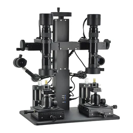
User Manual | Digital Comparison Mic roscope BD1601 www.lanoptik.com Chapter 4 Introduction to components Product schematic and part name ① Camera ② Movable hand wheel ③ Lens ④ Main light ⑤ Clamp holder ⑥ Rotatable ball head ⑦ Adjustable stage ⑧... -
Page 7: Product Parts Introduction
User Manual | Digital Comparison Mic roscope BD1601 www.lanoptik.com 4. 2 Product parts introduction 4.2.1 Camera Blue light flashing, output signal. ⑪Signal indicator Turn right (ON), turn on the camera; turn left ⑫Power switch (OFF), turn off the camera. Light does not shine, abnormal power supply;... -
Page 8: Lens
User Manual | Digital Comparison Mic roscope BD1601 www.lanoptik.com 4.2.3 Lens Focal length fixing screw: After loosening, turn the ○ 31 Focal length fixing screw Focal length adjustment ring to adjust the focus; after tightening, fix the magnification at the current position. -
Page 9: Clamp Holder
User Manual | Digital Comparison Mic roscope BD1601 www.lanoptik.com 4.2.5 Clamp holder Loosen the screw, the rotating block can be rotated 360°; ○ 51 Rotation adjustment screw tighten the screw to fix the current rotation angle Turn the screw clockwise to expand the clamp; turn the ○... -
Page 10: Adjustable Stage
User Manual | Digital Comparison Mic roscope BD1601 www.lanoptik.com 4.2.7 Adjustable stage Rotate clockwise, the stage rises; counterclockwise ○ 71 Z axis adjustment knob rotation, the stage descends; each turn of the knob, the stage moves 1.5mm, Z-axis travels 50mm. -
Page 11: Side Light
User Manual | Digital Comparison Mic roscope BD1601 www.lanoptik.com 4.2.9 Side light Loosen the knob to swing the position of the ○ 91 Adjustment knob articulated arm arbitrarily within a certain range; tighten the knob to fix the current position of the articulated arm. -
Page 12: Ports And Indicator Lights
User Manual | Digital Comparison Mic roscope BD1601 www.lanoptik.com 4.2.10 Ports and indicator lights Connected to the camera on the right through the network ○ 01 CAM1 interface cable to realize power supply and signal transmission to the camera. It is connected with the USB power interface of the main ○... -
Page 13: Chapter 5 Product Installation Method
User Manual | Digital Comparison Mic roscope BD1601 www.lanoptik.com Chapter 5 Product installation method 5.1 Stage assembly 5.1.1 Ball head and quick-mount rail assembly 1. Adjustable stage and ball head assembly 1)Place the ball head on the round platform, and the ball stud hole is aligned with the screw hole of the bottom plate. -
Page 14: Stage Clips Assembly
User Manual | Digital Comparison Mic roscope BD1601 www.lanoptik.com 5.1.3 Stage clips assembly 1. Install the stage clips in the form of image 6. (Image 6) 2. Screw the screws on the stage clips to the round platform with a screwdriver. (Image 7) -
Page 15: Cable Connection
User Manual | Digital Comparison Mic roscope BD1601 www.lanoptik.com 5.2 Cable connection 1、Network cable connection: Connect the camera to the bracket network port (the CAM1 or CAM2 interface is marked on the bracket) with the network cable. Camera on the right is connected with the CAM1 interface, and camera on the left is connected with the CAM2. -
Page 16: Chart 6 Instructions
User Manual | Digital Comparison Mic roscope BD1601 www.lanoptik.com Chart 6 Instructions 6.1 Start to use 1、Software installation (software installation and usage instructions, please refer to the software manual) 2、Stage assembly (Detailed reference 5.1) 3、Cable connection (Detailed reference 5.2) 6.2 Instructions 1、After the device is connected, open the software.
Need help?
Do you have a question about the BD1601 and is the answer not in the manual?
Questions and answers