Advertisement
Table of Contents
INSTALLATION
Note: If
concerned with line performance, contact AND Tech Support at
Ethernet cable around ferrite twice and clamp shut. Feed cable into wall mount bracket so that ferrite sits outside of device.
1.
Separate front assembly from bracket. Pull bottom of
bracket away from front assembly by gripping at removal aid
hole and then guide front assembly off top bracket studs.
Remove bag of screws from back of speaker magnet and save
for step [6].
Removal
Aid
2.
Mount bracket to wall using appropriate mounting
hardware. Use a minimum of 4 mounting holes.
a) Hold bracket on mounting surface in desired location,
aligning keyed mounting holes with structural features
(stud, etc.). Ensure the bracket is aligned by using a
level.
b) Ensure network cable access port on bracket is aligned
with the wiring source (junction box).
c)
Mark the location that the fasteners will attach to on
the wall.
d) Feed network cable (CAT5 or better) and any other
peripheral connections through access port in the
bracket.
e) Fasten the bracket at the previously marked locations.
Keyed Holes
Access
Port
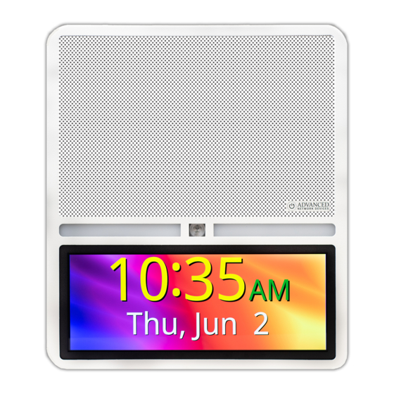
IP Speaker with HD Display (IPSWDHD-MW)
Advanced Network Devices • 3820 Ventura Dr. Arlington Hts. IL 60004
tech@anetd.com
• 847-463-2237 •
•
Version 1.0
tech@anetd.com
for a ferrite. Wrap last 20" of CAT5 or CAT6
3.
Connect network cable to the
internal circuit board on front baffle
assembly and connect any additional
wiring to the unit as needed.
4.
Hook front baffle assembly onto
top of bracket by guiding mounting
studs on front baffle assembly into
holes at top of bracket. Ensure sides of bracket fit inside both
sides of front baffle assembly and avoid scratching front
housing.
5.
Push bottom of front baffle assembly over bottom lip of
bracket.
6.
Install 2 screws, from bag set aside in step [1], into the
bottom of the front baffle assembly.
7.
Remove protective cover and tape from front of display.
www.anetd.com
8/19/2021
Quickstart
Advertisement
Table of Contents

Related Manuals for ADVANCED Network Devices IPSWDHD-MW


Summary of Contents for ADVANCED Network Devices IPSWDHD-MW
- Page 1 Fasten the bracket at the previously marked locations. Keyed Holes Remove protective cover and tape from front of display. Access Port Advanced Network Devices • 3820 Ventura Dr. Arlington Hts. IL 60004 tech@anetd.com • 847-463-2237 • www.anetd.com • Version 1.0...
- Page 2 Check the NTP server settings, and check that the Internet connection is working. ADDITIONAL RESOURCES User Support: https://www.anetd.com/user-support/ Technical Resources: https://www.anetd.com/user-support/technical-resources/ AND Limited Warranty: https://www.anetd.com/warranty/ AND Legal Disclaimer: https://www.anetd.com/legal/ Advanced Network Devices • 3820 Ventura Dr. Arlington Hts. IL 60004 tech@anetd.com • 847-463-2237 • www.anetd.com • Version 1.0 8/19/2021...
Need help?
Do you have a question about the IPSWDHD-MW and is the answer not in the manual?
Questions and answers