Table of Contents
Advertisement
Quick Links
Advertisement
Table of Contents

Related Manuals for Carrier Ziton ZP3

Summary of Contents for Carrier Ziton ZP3
- Page 1 ZP3 Fire Panel User Guide P/N 503-1160ZE-U-14 • ISS 08JUL21...
- Page 2 Copyright © 2021 Carrier. All rights reserved. Trademarks and The ZP3 Fire Panel name and logo are trademarks of Carrier. patents Other trade names used in this document may be trademarks or registered trademarks of the manufacturers or vendors of the respective products.
-
Page 3: Table Of Contents
Content Important information iii European regulations for construction products iii European standards for fire control and indicating equipment iv Advisory messages iv List of abbreviations and acronyms v Associated publications and references vi System overview 1 Basic system features 2 Operation 3 Sensors and devices 3 Maintenance features 5... - Page 4 LCD display 19 Overview 19 Alarms by zone 19 Scrolling alarms 19 Alarms by device 20 Zone screen 20 Point screen 21 Operator response 23 Fire alarms 23 Fault alarms 24 Disabling system elements 25 Other alarms 26 Operator menu 28 Introduction 28 Menu access 28 Menu structure 30...
-
Page 5: Important Information
Certification body 1134 Manufacturer Carrier Manufacturing Poland Spòlka Z o.o., Ul. Kolejowa 24, 39-100 Ropczyce, Poland. Authorized EU manufacturing representative: Carrier Fire & Security B.V., Kelvinstraat 7, 6003 DH Weert, Netherlands. Year of first CE marking Declaration of Performance number 360-3301-0199... -
Page 6: European Standards For Fire Control And Indicating Equipment
Standardized Input/output interface Product warnings and disclaimers THESE PRODUCTS ARE INTENDED FOR SALE TO AND INSTALLATION BY QUALIFIED PROFESSIONALS. CARRIER FIRE & SECURITY B.V. CANNOT PROVIDE ANY ASSURANCE THAT ANY PERSON OR ENTITY BUYING ITS PRODUCTS, INCLUDING ANY “AUTHORIZED DEALER” OR “AUTHORIZED RESELLER”, IS PROPERLY TRAINED OR EXPERIENCED TO CORRECTLY... -
Page 7: Advisory Messages
Advisory messages Advisory messages alert you to conditions or practices that can cause unwanted results. The advisory messages used in this document are shown and described below. WARNING: Warning messages advise you of hazards that could result in injury or loss of life. They tell you which actions to take or to avoid in order to prevent the injury or loss of life. -
Page 8: Associated Publications And References
Associated publications and references The documents, or parts thereof, that are referenced in this manual are listed below. Document title Document number British Standard: Fire Detection and Alarm systems for BS5839-1 2002 buildings, Part 1. Code of practice for system design, installation and servicing ZP3 Fire Control Panel Installation, Commissioning and 503-1160ZE-I-13... -
Page 9: System Overview
System overview The ZP3 is a complete intelligent fire detection system designed to protect life and property. Each system is an individual design, based upon modular ZP components. The ZP3 detects the presence of smoke or fire, raises alarms, and accurately indicates the location of the fire. -
Page 10: Basic System Features
Basic system features The ZP3 system incorporates a wide range of features and capabilities, including these: • The ZP3 incorporates the proven ZP system of automatic contamination adjustment for each sensor. This recalibrates each sensor as it becomes contaminated, and provides a constant sensitivity even when sensors are dirty. -
Page 11: Operation
Operation The panel incorporates a simple and effective operator interface that includes a 160-character LCD display. Together with zone LEDs and function LEDs, these indications give a clear and unambiguous indication of all alarms and reports. All control functions are menu driven, and three access levels are protected by passwords. - Page 12 Type 54 emulation Type 54 emulated devices improve functionality: A type 54 emulated device can be mapped to disable any other line device. This is reported on the panel as an event and updated in the Event archive. The ZP3 panel, when fitted with the software shown in the specification supports the following sensors and devices.
-
Page 13: Maintenance Features
Number Description ZP786ex Intrinsically-safe call point ZP740ex Intrinsically-safe interface unit ZP35-ECU Extinguishing control units ZS200 High sensitivity aspirating smoke detectors ZX832 Multisensor fire detector (optional) * Used with the ZP471A and ZP472A Radio interface units only (see “Total Loss of Power alarm” on page 6). -
Page 14: Total Loss Of Power Alarm
Total Loss of Power alarm The ZP3 panel is fitted with a Total Loss of Power alarm feature. This feature is a prewired, independent circuit that turns on the Common Fault and System Fault LEDs and sounds a buzzer in the event of total loss of power. This condition occurs when the mains power has been lost and the battery has been depleted to the extent that load shedding has occurred, prior to the entire panel being shut down. -
Page 15: Day/Night Capability
Day/night capability Day/night control provides separate programmes for day and night modes. Different sensor sensitivity, alarm selection, alarm evaluation delays, and fire brigade responses can be configured. Configuration A programming or configuration utility allows any “cause-and-effect” requirement to be configured. Each panel can have up to 896 physical outputs that are software linked to as many as 2,000 inputs in any arrangement. -
Page 16: Principle Of Operation
Principle of operation Sensing devices, e.g. heat and smoke detectors, manual call points, etc. are grouped into zones, and programmed with text labels to indicate their location. The control panel continually checks each fire or smoke sensor, call point, or other device attached to the ZP-loop, every 2 seconds. -
Page 17: Zp3 Fire Control Panel
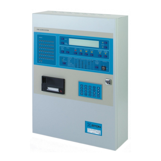
ZP3 Fire control panel In addition to operating all the sensors, sounders, and other devices in the system, the control panel provides the interface for the operator by means of its front panel fascia. Figure 2 below shows a typical ZP3 Fire Control Panel. Figure 2: ZP3 Fire control panel ZP3 Fire Panel User Guide... -
Page 18: Panel Fascia
Panel fascia The ZP3 system is operated by means of the controls and indicators on the ZP3 panel Fascia as shown in Figure 3 below. In some systems, the operator controls the system from a Remote Display Unit and not from the panel fascia. This is identical to the control panel, but is usually located in some other area, such as a control room. - Page 19 Where more than one type of alarm is present simultaneously, then the highest priority alarm displays automatically. The priority order is: 1. Fire 2. Fault 3. Disabled 4. Other To view other categories of alarm, press the relevant button as described below. After viewing lower-priority alarms using the alarm view buttons, the system times out and automatically returns to the current highest priority alarm.
- Page 20 Fire indicator The Fire indicator illuminates when any fire alarm is received by, or is currently present, in the system. The indicator flashes for a new alarm, and becomes steady after an alarm has been accepted. New alarms must be responded to immediately.
-
Page 21: Navigation Buttons
Figure 5: Zonal fire indicators LOCAL ZONES Zonal fire indicators LCD display The LCD display automatically indicates an alarm with a text message, which identifies the zone in which the alarm occurred. The LCD display can show two alarms simultaneously. When more than two alarms are present at the same time, they can be scrolled using the Up and Down scroll buttons. -
Page 22: Main Operating Controls
View Points button Press the View Points button to access the Device screen, which shows the alarms by device (point), together with their address, location, device type, the nature of the alarm, and the programmed device message. Help button Press the Help button to display on-screen operating instructions for the ZP3 panel. -
Page 23: Status Indicators
Sound Alarms button Press the Sound Alarms button to activate all the sounders in the building. This can be done, for example, to sound a general alert or to restore sounders that were silenced. Restore Disabled Alarms button In Software version 3.10 and earlier, press the Restore Disabled Alarms button to restore disabled sounders. - Page 24 The status indicators are organized into the columns shown in Figure 8 on page 15, and the conditions shown in Table 7 below are indicated. Table 7: Status indicator conditions Indicator Remarks Power On Indicates that the ZP3 panel has power, either from the mains or from the standby battery.
-
Page 25: Display Of Alarms
Display of alarms Overview See Figure 9 below. Alarms are indicated both audibly and visibly on the fascia of the panel (or remote display panel). Audible indication is by means of a built-in panel buzzer. Visible indication is by means of illuminated LED indicators and descriptive text on the LCD display. -
Page 26: Disabled Alarms
Disabled alarms Events such as zones, sensors, or sounders being disabled are shown by means of the common Disabled LED and the LCD display. The LCD display can be cleared with the Reset button, but as long as the devices remain disabled, the common Disabled indicator remains lit. -
Page 27: Lcd Display
LCD display Overview ZP3 panels use a carefully structured reporting system for alarms, faults, and other events. Information is displayed on a 160-character LCD display as shown in Figure 10 below. The display has two alarm screens; the zone screen, which shows alarms by zone, and the point screen, which shows alarms by device. -
Page 28: Alarms By Device
Alarms by device Press View Points to see current alarms by device. The device screen displays the exact address of the View Points button device, and a message with its exact location. Zone screen The following paragraphs describe how to read the LCD display when it indicates an alarm. -
Page 29: Point Screen
• The time of the alarm, for example 06:44, is shown at the right side of the line (optional). Note: In the default zone display, line 3 shows the last alarm received. Line 4: Confirms type of alarm shown The type of alarm, for example “FIRE”, is shown above the associated common alarm indicator and alarm view button. - Page 30 Line 3: Zone details • The zone number for this device is displayed at the beginning of the line, for example “Z001”, followed by the zone message for that location. • The time of the alarm (optional) is displayed at the end of the line. Line 4: Confirms type of alarm shown •...
-
Page 31: Operator Response
Operator response Fire alarms A fire alarm displays on the panel as described in Table 8 below. The actions carried out upon receipt of a fire alarm depend upon the fire alarm procedures at the site where the alarm occurred. The following are generic guidelines only. Table 8: Fire alarms —... -
Page 32: Fault Alarms
For example, remove smoke from the detectors or replace the glass in a call point. When you press Reset, the system restores to its normal state. Fault alarms A fault alarm displays on the panel as described in Table 9 below. The actions carried out upon receipt of a fault alarm depend upon the procedures at the site where the system is installed. -
Page 33: Disabling System Elements
3. Record the action taken in the logbook. 4. Press the Reset button after the fault has been rectified. The system restores to normal. Disabling system elements Zones, sensors, call points, sounders, control outputs, outputs, and remote manned centre alarms can be manually disabled for maintenance or other purposes. -
Page 34: Other Alarms
The auto-enable feature (also called disable for a period) is detailed in Table 13 below. Table 13: Auto-enable (disable for a period) Menu path Maintenance > Edit or View Disabled (Points, Zones) Purpose This menu lets you temporarily disable an address in half hour intervals. This allows multiple zones and line input devices to be disabled but not panel or panel bus outputs. - Page 35 Description Remarks Delayed functions Delayed LED illuminated for those functions that are programmed to operate in response to the alarm, and are configured for delayed operation. These could be remote centre alarms or control functions. Types of alarm Other alarms can be categorized as shown in Table 15 below). Table 15: Other alarms —...
-
Page 36: Operator Menu
Operator menu Introduction The panel has built-in software functions for carrying out routine operator functions and system checks. These functions are accessed via the operator menu, using the panel keypad. This section describes these functions and how to use them. When using a menu, the LCD screen displays the menu items in place of any alarms or events that would normally appear on the screen. - Page 37 Table 16: Keypad description Button Name Description Numeric buttons Used to enter the number sequences Menu button Gives access to the Main Menu Enter button Used to confirm data entry and save data Escape button Exits a function and returns to the previous level Home button Exits all menus and returns to the system...
-
Page 38: Menu Structure
45 seconds, and if a software function has been started and but completed, then the time-out is 12 minutes. Menu structure The operator menu structure is displayed as a menu tree, and shown in Figure 14 below. Items that are grouped together are options that appear together on a menu, and items that are open-ended implement a software function. - Page 39 Table 18: Reports to display Menu path Operator > Reports to display Purpose This menu provides a selection of reports to view on the LCD. Report messages can be scrolled manually. Point status This option lets you view the status report of any device attached to the panel Z-loops on the LCD.
-
Page 40: Operator Maintenance
Operator maintenance Overview The owner of a fire detection system is responsible for ensuring that it is correctly maintained so that it is in proper working condition at all times. This involves arranging for the system to be checked, tested, and serviced as described in this manual. - Page 41 Making sure that a clear space of at least 500 mm is preserved around and below all fire detectors. Making sure that all manual call points remain unobstructed and conspicuous. Making sure to communicate with those responsible for changes to, or maintenance of, the building to ensure that changes do not compromise the effectiveness of the system.
-
Page 42: Routine Maintenance
Record keeping The operator should maintain a logbook (see document 503-1842ZE-0-02) at the control panel. A record of all alarms, events, checks, tests, and repairs should be entered in this logbook. Routine maintenance Note: Occupants of the building and anyone receiving remote alarm signals, such as the fire department, must be informed before starting with the test or routine maintenance. - Page 43 Caution: Before testing the operator must be aware both of the operation of all devices fitted to any auxiliary circuits and the consequences of their operation. For example a connection to call the fire brigade. Do the following checks every week: 1.
Need help?
Do you have a question about the Ziton ZP3 and is the answer not in the manual?
Questions and answers