Table of Contents
Advertisement
AIR CONDITIONER
AC052FBMDEH/EU,AC071FBMDEH/EU,
AC090FBMDEH/EU,AC100FBMDEH/EU
AC071FCADEH/EU
AC090FCADEH/EU
AC100FCADEH/EU
AC100FCADGH/EU
Refer to the service manual in the GSPN(see the rear cover) for the more information.
SYSTEM AIR CONDITIONER
Model : AC052FBMDEH/EU
AC052FCADEH/EU
INDOOR UNIT
AC071FBMDEH/EU
AC090FBMDEH/EU
AC100FBMDEH/EU
CONTENTS
1. Precautions
2. Product Specifications
3. Disassembly and Reassembly
4. Troubleshooting
5. PCB Diagram
6. Wiring Diagram
7. Schematic Diagram
8. Reference Sheet
OUTDOOR UNIT
AC052FCADEH/EU
AC071FCADEH/EU
AC090FCADEH/EU
AC100FCADEH/EU
AC100FCADGH/EU
Advertisement
Table of Contents

Related Manuals for Samsung AC052FBMDEH/EU


Summary of Contents for Samsung AC052FBMDEH/EU
- Page 1 SYSTEM AIR CONDITIONER INDOOR UNIT OUTDOOR UNIT Model : AC052FBMDEH/EU AC052FCADEH/EU AC071FBMDEH/EU AC071FCADEH/EU AC090FBMDEH/EU AC090FCADEH/EU AC100FBMDEH/EU AC100FCADEH/EU AC100FCADGH/EU AIR CONDITIONER CONTENTS 1. Precautions 2. Product Specifications 3. Disassembly and Reassembly AC052FBMDEH/EU,AC071FBMDEH/EU, AC090FBMDEH/EU,AC100FBMDEH/EU 4. Troubleshooting 5. PCB Diagram AC071FCADEH/EU 6. Wiring Diagram 7.
-
Page 2: Table Of Contents
4-5-8 Coil temperature sensor error 4-18 ........................... 4-5-9 Fan error 4-19 ..................... 4-5-10 DC-Link voltage sensor error 4-20 ...................... 4-5-11 O.C.(Over Current) error 4-21 ......................4-5-12 Communication error 4-22 ......................4-5-13 Compressor start error 4-23 ......................4-5-14 Compressor lock error 4-24 Samsung Electronics... - Page 3 6-2 Outdoor Unit 17. Schematic Diagram ....................................................7-1 Indoor Unit ..........................7-1-1 MAIN PCB ........................7-1-2 Outdoor Unit PCB 8. Reference Sheet ..................................................8-1 Index for Model Name ......................8-2 Refrigerating Cycle Diagram ........................... 8-3 Pressure Graph Samsung Electronics...
-
Page 4: Precautions
Check whether the installation location is at least two meters away from other electronic products such as TV, video, or audio. – Otherwise, the video quality might be degraded or noise might be generated. Do not let end users repair the products themselves. – Unauthorized disassembly might cause electric shock or fire. Samsung Electronics... -
Page 5: Precautions Related To Product Safety
– Release the high pressure and low pressure valve caps. – Close the high pressure valve completely using an L-wrench – After about two minutes, close the low pressure valve completely. – Stop running the air conditioner. – Separate the connecting pipe. Samsung Electronics... -
Page 6: Product Specifications
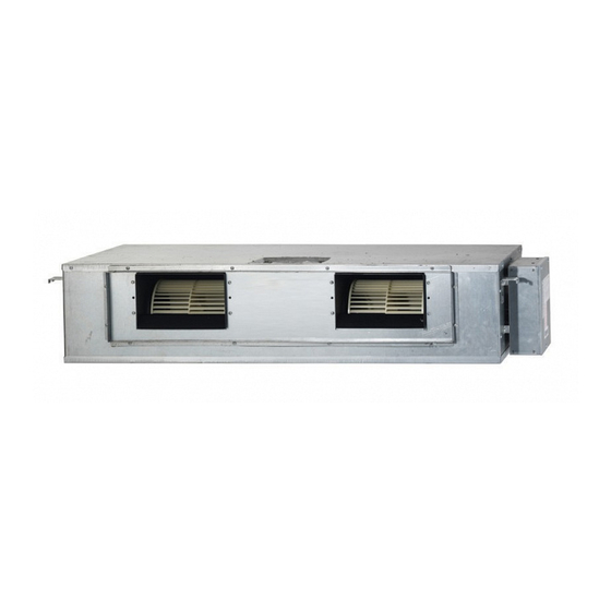
It can give the benefit to the installers and aries the reliability of the air conditioner. Long Ambient Operation(In Low Temperature) It can arise the reliability and the capacity of the air conditioner, especially operated in low temperature. Eco-friendly Product(Lead-Free, RoHS, WEEE) Samsung Electronics... - Page 7 2-2 Product Specifications AC052FBMDEH/EU AC071FBMDEH/EU ITEM AC052FCADEH/EU AC071FCADEH/EU Indoor Unit Outdoor Unit IMAGE Remote Controller Power Specifications 1Φ, 220~240V,50Hz Indoor W x H x D 900x260x480 1150x480x260 Size Outdoor W x H x D 750x548x285 880x310x798 Indoor Unit 28.0 31.5...
-
Page 8: Product Specifications
In case of strongest air Heating) Outdoor blow Refrigerant (R410A) 3000 3000 3100 Liquid 3/8" 3/8" 3/8" Connecting Pipe 5/8" 5/8" 5/8" Additional Refrigernat (R410A) Standard Extension length(Total) Extension length(Elevation) 011034-15617C- Product Option 011034-15617C-276470-370000 275A64-350000 Option Code 020000-100000- Installation Option 020000-100000-200000-300000 200000-300000 Samsung Electronics... -
Page 9: Specifications Of Optional Items
Insulation-Hose D DB62-11028E Insulation-Tube Out DB62-11028F Cable-tie DB65-10088C Grommet-Hanger DB63-00237A Ass'y Drain Hose Joint DB94-03287A DB73-20134A RUBBER LEG Outdoor unit DB67-20011A AC071FCADEH DB67-00477A AC052FCADEH DRAIN PLUG AC090FCADEH DB67-00806A AC100FCADEH AC100FCADGH AC090FCADEH DB98-32793A AC100FACADEH AC100FACADGH Installation manual AC052FCADEH DB68-03464A AC071FCADEH Samsung Electronics... - Page 10 STS 2S-2x10 Tapped Screw 2S-4x12 Tapped Screw Concealed type User’s manual DB98-05160A Installation manual DB98-05186A DB39-00223A Wire kit (MRW-10A) DB93-01066A Receiver & display unit (MRK-A00) M4x12 Tapped Screw Cable-tie Standard type User’s manual DB98-04184A Installation manual DB98-04189A DB39-00223A Wire kit (MRW-10A) Samsung Electronics...
- Page 11 DB97-14333C Wired remote controller (MWR-WH02) Cable tie DB65-10088B Cable clamp DB65-10074E M4×16 Tapped Screw 6002-000474 Indoor unit power drawing cable DB39-00221A Optional Communication cable of thewired remote DB39-00933A controller Wire joint DB39-90020A User’s manual DB98-25179A Installation manual DB98-25180A Samsung Electronics...
- Page 12 Accessories (cont.) ■ Centralized controller Item Descriptions Code-No. Q'TY Remark DB93-03425C Centralized controller (MCM-A202) Cable tie DB65-10088B Cable clamp DB65-10074E Optional M4x16 Tapped Screw 6002-000474 User’s manual DB98-12721A Installation manual DB98-25773A Samsung Electronics...
- Page 13 Function controller (MCM-A100) Cable tie DB65-10088B Cable clamp DB65-10074E Optional M4x16 Tapped Screw 6002-000474 User’s manual DB98-27317A Installation manual DB98-27315A ■ Transmitter Item Descriptions Code-No. Q'TY Remark DB97-00647P Transmitter (MIM-B04A) Transmitter power cable DB39-00378D Optional Transmitter communication cable DB39-00253D Samsung Electronics...
- Page 14 Accessories (cont.) ■ DMS(Date Management Server) Item Descriptions Code-No. Q'TY Remark DB93-03709B (MIM-D00) Cable tie DB65-10088B Cable clamp DB65-10074D Optional M4x16 Tapped Screw 6002-000474 Bottom hook DB73-00320A User’s manual DB98-27317A Installation manual DB98-27315A Samsung Electronics...
-
Page 15: Disassembly And Reassembly
3. Disassembly and Reassembly Necessary Tools Item Remarks +SCREW DRIVER Adjustable Wrench (8mm, 10mm, 13mm) Samsung Electronics... -
Page 16: Indoor Unit
1) After disassembling 16 places indicating screws, detach Ass'y Cabi Bottom Blower. (Use +Screw Driver) 2) Detach the Motor Fan connector from the BLDC PCB. 3) After disassembling 2 places indicating screws, detach the 2 Fan Case. (Use +Screw Driver) Samsung Electronics... - Page 17 4) After disassembling 2 places indicating screws, detach Fan Motor and Blower from the set. Control In 1) After disassembling 3 Indicating screw, detach the Cover control. (Use +Screw Driver) 2) Detach the Motor-Fan and Sensor Connector from the PCB. Samsung Electronics...
- Page 18 Parts Procedure Remark 3) Disassemble 4 indicating screws and detach Control In from the set. Drain Pan Work is possible when Disassembling the Ass'y Cabi Bottom Blower. 1) Disassemble 7 indicating screws and detach Ass'y Cabi Bottom Drain.. Samsung Electronics...
- Page 19 1) Disassemble 4 indicating screws and detach the Drain Pan. (Use +Screw Driver) (2 screws each at left and right side). Evap Work is possible when Disassembling the Ass'y Drain Pan. 1) Disassemble 5 indicating screws to detach Cover Pipe. (Use +Screw Driver) Samsung Electronics...
- Page 20 2) Disassemble Sensor on the Evap. 3) Disassemble 4 indicating screws which are in the near of Hanger Plate to detach the Evap. (Use +Screw Driver) (2 screws each at left and right side) It needs 2 peoples.. Samsung Electronics...
-
Page 21: Outdoor Unit
1) loosen 1 pcs screw of cover control,and detach it. 2) loosen 5 pcs screws on both right and left cabniet side edges and to detach the cover-top 3) Loosen 7 screwsfixed to disassemble cabi-front , and detach it. Samsung Electronics... - Page 22 Parts Procedure Remark common work 4) loosen 7 screws to disassemble the cabi- right ,and detach it. 5) loosen 2 screws to disassemble steel-bar. 6) loosen 3 screws to disassemble cabi-left. Samsung Electronics...
- Page 23 Procedure Remark fan&motor 1) loosen 1 screw as indication and detached the fan. 2) loosen 4 pcs motor screws and disconnect the wire betwwen assy control out and motor. 3) loosen 2 pcs bracket-motor screw and detach it. Samsung Electronics...
- Page 24 Heat exchanger 1) Release the refrigerant at first 2) Looosen fixing screw on both side. 3) disaessembly the pipes in both inlet and outlet with welding torch. 4) detach the heat exchanger. Samsung Electronics 3-10...
- Page 25 Parts Procedure Remark compressor 1) disconnect the compressor lead wire . 2)disassembly the felt comp sound. loosen the 3 bolts at the bottom of 3-11 Samsung Electronics...
- Page 26 AC071FCADEH/EU Parts Procedure Remark Common Work 1) Loosen 1 fixing screw of the Cover-Control and detach the Cover Control. 2) Loosen each 7 fixing screws and detach the Cabinet Upper. Samsung Electronics 3-12...
- Page 27 Parts Procedure Remark 3) Loosen 2 screws fixed to assemble Control Box with Cabinet-Side RH. 4) Loosen fixing screws and detach the Cabinet-Side RH. 5) Loosen 2 screws fixed on the Guide Condenser. 3-13 Samsung Electronics...
- Page 28 Parts Procedure Remark 6) Loosen fixing screws of the Cabinet Front. Samsung Electronics 3-14...
- Page 29 2) Detach the Fan Propeller. 3) Loosen 4 fixing screws to detach the Motor. 4) Disconnect the wire between ASS'Y Control Out and Motor. 5) Loosen 2 fixing bolts and detach the Bracket Motor. 3-15 Samsung Electronics...
- Page 30 2) Loosen fixing screw on both sides. 3) Disassemble the pipes in both inlet and outlet with welding torch. 4) Detach the Heat Exchanger. 5) Loosen 4 bolts fixed to assemble Valve Service with Bracket Valve like the picture on the right side. Samsung Electronics 3-16...
- Page 31 Procedure Remark Compressor 1) Loosen the fixing nut and detach the Compressor Lead Wire. 2) Disassemble the Felt Compressor Sound. 3) Loosen the 3 bolts at the bottom of Compressor like the picture on the right side. 3-17 Samsung Electronics...
- Page 32 Cabinet Front RH. (Use +Screw Driver) Cabi Top 1) Unscrew and remove 9 screws on each side of the Cabinet-Top. (Use +Screw Driver) Cabi Install Front 1) Unscrew and remove 1 screw in the Cabinet-Install Front. (Use +Screw Driver) Samsung Electronics 3-18...
- Page 33 2) Unscrew and remove 4 screws in the Guard Cond. (Use +Screw Driver) Cabi Back RH 1) Pull the sensor from Cabi Back RH. 2) Unscrew and remove 4 screws on each side of the Cabinet Back RH. (Use +Screw Driver) 3-19 Samsung Electronics...
- Page 34 Parts Procedure Remark Cabi Install Back 1) Unscrew and remove 1 screw in the Cabinet-Install Back. (Use +Screw Driver) Cabi Front LF 1) Unscrew and remove 10 screws in the Cabinet-Front LF. (Use +Screw Driver) Samsung Electronics 3-20...
- Page 35 Parts Procedure Remark 1) Turn 2 mounting nuts as shown in the picture and remove it. (Use Adjustable Wrench) 3-21 Samsung Electronics...
- Page 36 1) Separate the Fan Propeller. 2) Unscrew and remove the 4 Motor mounting screws. (Use +Screw Driver) 3) Disconnect the Motor wire From Ass'y Control Out. Bracket Motor 1) Unscrew and remove 2 mounting screws in Bracket Motor. (Use +Screw Driver) Samsung Electronics 3-22...
- Page 37 Parts Procedure Remark Control Out 1) Disconnect 4 Connecters From Ass'y Control Out. 2) Unscrew and remove 1 mounting screw in Control Out. (Use +Screw Driver) 3) Separate Ass'y Control Out. 3-23 Samsung Electronics...
- Page 38 Service Valve. (Use +Screw Driver) 4) Separate the pipe from the Entrance/Exit using a welder. When removing the compressor, Heat Exchanger, and Pipe, purge the Coolant inside the Compressor completely and remove the pipe with a welding flame. Samsung Electronics 3-24...
- Page 39 1) Unscrew and remove 2 mounting screws in Service Valve. (Use +Screw Driver) 2) Separate the pipe from the Entrance/Exit using a welder. Compressor 1) Unscrew and remove 1 mounting nut in Cover Terminal. (Use Adjustable Wrench) 2) Separate the Compressor Felt Sound. 3-25 Samsung Electronics...
- Page 40 3) As shown in the picture, unscrew and remove 3 mounting screws from the bottom. (Use Adjustable Wrench) Cond Out 1) Unscrew and remove 3 screws on each side of the Assy Cond Out. (Use +Screw Driver) 2) Separate the Compressor Felt Sound. Samsung Electronics 3-26...
-
Page 41: Troubleshooting
Error of setting option switches for optional accessories EEPROM option error ◑ ◑ ◑ ◑ ◑ ● : ON, ◑ : Flickering, X : OFF ※ If you turn off the air conditioner when the LED is flickering, the LED is also turned off. Samsung Electronics... -
Page 42: Wired Remocon Error Display(Com2)
Outdoor unit Capacity Setup option error Communication error between Indoor unit and wired remote control Communication error between Master and Slave wired remote control Wired remote control error COM1/COM2 Cross-installed error Error of setting option for wired remote control COM2 Samsung Electronics... -
Page 43: Outdoor Led Error Display And Check Method
OTP error Compressor rotation error Operation condition secession DC-Link voltage sensor error I_Trip error GAS Leak error Power Cable miss connection Power ON reset(1sec) Capacity miss match Test Operation at Cooling Mode Test Operation at Heating Mode Blink Samsung Electronics... -
Page 44: Setting Option Setup Method
You can only check the indoor unit option code in Slave wired remote controller. Setting indoor unit option code is possible when one indoor unit is connected. If more than 2 indoor units are connected, you can only check the Master indoor unit option code. Samsung Electronics... - Page 45 Press the button to exit. You will move to the menu selection display. Press the button anytime during setup to exit without setting. Setting main/group address of an indoor unit is available only with a master wired remote controller. Samsung Electronics...
- Page 46 SEG12 HOT COIL RESERVED RESERVED Master / Slave Drain pump SEG13 SEG14 SEG15 SEG16 SEG17 SEG18 Number of hours External control output RESERVED Buzzer External control using filter SEG19 SEG20 SEG21 Individual control RESERVED of a remote controller Samsung Electronics...
- Page 47 Setting an indoor unit DIP option code is available when there is one on one connection between a wired remote controller and an indoor unit. Indoor unit DIP option code will not be applied if you don’t press the button. Samsung Electronics...
- Page 48 SEG8 SEG9 SEG10 SEG11 SEG12 AC052FBMDEH AC052FCADEH AC071FBMDEH AC071FCADEH AC090FBMDEH AC090FCADEH AC100FBMDEH AC100FCADEH AC100FBMDEH AC100FCADGH Model SEG13 SEG14 SEG15 SEG16 SEG17 SEG18 SEG19 SEG20 SEG21 SEG22 SEG23 SEG24 AC052FBMDEH AC052FCADEH AC071FBMDEH AC071FCADEH AC090FBMDEH AC090FCADEH AC100FBMDEH AC100FCADEH AC100FBMDEH AC100FCADGH Samsung Electronics...
-
Page 49: Items To Be Checked First
The compressor operates in a reverse cycle to Indoor fan and outdoor fan stop operation remove exterior ice in a HEAT mode, and intermittently in a HEAT mode. indoor fan and outdoor fan do not operate intermittently for within 20% of the total heater operation. Samsung Electronics... -
Page 50: Fault Diagnosis By Symptom
Check DIP SW in the wired remote controller Set DIP SW correctly. Is there any error display on the wired Check each item according to error code list. remote controller Check the setting temperature Samsung Electronics 4-10... -
Page 51: The Outdoor Unit Power Supply Error
#1 and #3 Are wire and socket connected Check and correct the wiring Error 469 display Error 469 display correctly? CN05,06,07 TAB (Table No. 19) (Table No. 19) terminal(EMI PCB), CN20(INVERTER PCB) Check the M/C 4-11 Samsung Electronics... -
Page 52: The Outdoor Unit Fan Error
Is the Pin voltage #6 - #3 of CN40 and 41changed Exchange INVERTER PCB high(4-5V) and low(0-1V) in case ofmaking manual rotation slowly? Is the Pin voltage #7 - #3 of CN40 and 41 low(0-1V) in Exchange the FAN motor normal rotation? Exchange the FAN motor Samsung Electronics 4-12... -
Page 53: Total Current Trip Error
Is the installation of indoor unit good? Exchange the compressor Does the compressor rotate normally? Open valve screw to the end Are the service valves full opened? Is AC power voltage normal during Check AC power source thecompressor in operation? Exchange INVERTER PCB 4-13 Samsung Electronics... -
Page 54: In Case Of Heating At The Cooling Mode Or Cooling At The Heating Mode
Check the resistance value of 4-WAY 4-WAY valve coil error valve coil Dose thevoltage of AC220V apply to the Exchangethe outdoor PCB connector of 4-WAY valve coil during the operation? Go to the next page 4-WAY valve main body error Samsung Electronics 4-14... - Page 55 Load estimation error of compressor? Is theoutdoor fan Connect the connector connectedcorrectly? Check the resistance value of Outdoor fan error outdoor fan Is theoutdoor fan Check the motor wire connectedcorrectly? Outdoor PCB error 4-15 Samsung Electronics...
-
Page 56: Outdoor Temperature Sensor Error
(Refer to the R/T TABLE) Exchange the sensor Is the resistance valueof sensor connection pull_up 18K? Exchange the PCB Exchange the PCB Normal operation Exit 400.0 350.0 300.0 250.0 200.0 150.0 100.0 50.0 Samsung Electronics 4-16... -
Page 57: Discharge Temperature Sensor Error
(Refer to the R/T TABLE) Exchange the sensor Is the resistance valueof sensor connection pull_up 24K? Exchange the PCB Exchange the PCB Normal operation Exit 600.0 500.0 400.0 300.0 200.0 100.0 4-17 Samsung Electronics... -
Page 58: Coil Temperature Sensor Error
(Refer to the R/T TABLE) Exchange the sensor Is the resistance valueof sensor connection pull_up 18.2K? Exchange the PCB Exchange the PCB Normal operation Exit 400.0 350.0 300.0 250.0 200.0 150.0 100.0 50.0 Samsung Electronics 4-18... -
Page 59: Fan Error
4) Is the resistance value of sensor connection pull_up correct? 2. Troubleshooting procedure Isn't the Fan locked? Remove the Fan lock Is the connector connected correctly? Connect the connector Is the color of Fan wire matched correctly? Exchange the Fan Exchange the PCB Normal operation Exit 4-19 Samsung Electronics... -
Page 60: Dc-Link Voltage Sensor Error
1) Is the connection of R, S, T power wire normal? 2) Are Relay RY21 and R200 on the INVERTER PCB mounted normally? 2. Troubleshooting procedure Are connection of the wire from INVERTER PBA to Check and correct the wire connection EMI PBA normal? Exchange INVERTER PCB Samsung Electronics 4-20... -
Page 61: Over Current) Error
Is insuration resistance between each compressor Exchange the compressor terminal and body normal? Exchange the compressor Does the compressor rotate normally? Did AC power voltage interruption happen during Check AC power source the compressor in operation? Exchange INVERTER PCB 4-21 Samsung Electronics... -
Page 62: Communication Error
Correct the wrong wiring cable wiring error? Correct the compressor wire connection Is the connection of communication cable normal? Is insuration resistance between each compressor Correct the connection of communication cable terminal and body normal? Exchange the outdoor unit PCB Samsung Electronics 4-22... -
Page 63: Compressor Start Error
Exchange the compressor (u v, v w, w u) normal? Is the compressor body and interphase Exchange the compressor resistance insulated? Is the connection cable for thecompressor and Correct the cable connection power terminal normal? Exchange the PCB 4-23 Samsung Electronics... -
Page 64: Compressor Lock Error
(u v, v w, w u) normal? Is the compressor body and interphase Exchange the compressor resistance insulated? Is the connection cable for the compressor and Correct the cable connection power terminal normal? Exchange the outdoor unit PCB Samsung Electronics 4-24... -
Page 65: Dc Link Over Voltage/Low Voltage Error
Exchange M/C Is each contact resistance normal? (less than 0.1ohm) Exchange INVERTER PCB Does the error reappear frequently The cause of this error may be power source trouble as like power interruption.Check the power source 4-25 Samsung Electronics... -
Page 66: Pcb Inspection Method
•Controller trouble inside of FAN operation checking 1) Is the FAN motor running? Press the ON/OFF button. 2) Is the connection of CN73 normal? the fan motor •Connector trouble of CN73 1. FAN Speed[HIGH] 2. FAN mode Samsung Electronics 4-26... -
Page 67: Outdoor Detailed Inspection Procedure
EMI PCB and INVERTER PCB upper side pin of '~' marking pins 2) Is DC Link voltage 450-510V? Check IGBT module pins marking voltage near C70 Check BLDC fan 1) See 12-2-3 The Outdoor unit Fan error (Fault Diagnosis) 4-27 Samsung Electronics... -
Page 68: Main Part Inspection Method
BLUE - BLACK 10KΩ ~ 50KΩ pulse ORANGE - BLACK 10KΩ ~ 50KΩ reverse Abnormal ∞,0Ω...Open or Short Outdoor Unit 4way Valve Solenoid Measure sensor resistance with a multimeter Normal At the normal temperature(10˚C~30˚C) 1.6KΩ±15% Abnormal ∞,0Ω...Open or Short Samsung Electronics 4-28... -
Page 69: Indoor Unit
5. PCB Diagram 5-1 PCB Diagram 5-1-1 Indoor Unit 19 18 15 20 17 16 12 13 Samsung Electronics... - Page 70 Display : SMW200-11(WHT) : SMW200-11(WHT) Power : YW396-03AV(WHT) External Control(Display Part) : SMW250-04(RED) Transformer Out : YW396-03AV(WHT) HALL IC : SMW250-03(BLU) Main Power In : YW396-03AV(BLU) MICOM Download : SMW200-10(WHT) Power : YW396-03AV(BLU) Indoor/Outdoor Communication : YW396-02(RED) Transformer In : SMW250-03(RED) Samsung Electronics...
- Page 71 Samsung Electronics...
- Page 72 5-1-2 Outdoor Unit PCB (cont.) ■ MAIN PCB AC052FCADEH/EU ① 4WAY CONNECTOR YAW396-03AV WHT SMW200-28C WHT ② MAIN-SUB CONNECTOR SMW250-02 RED ③ 485 COMMUNICATION CONNECTOR ④ OLP THERMISTOR CONNECTOR SMAW250-02 WHT SMW200-28C WHT ⑤ S-NET CONNECTOR ⑥ EEV-A CONNECTOR SMAW250-06 RED SMW250-06 BLU ⑦ OUT/DIS/COND CONNECTOR SMAW200-10P BLK ⑧ DOWNLOAD-MAIN CONNECTOR ⑨ CENTRAL-CTL CONNECTOR SMW200-05P WHT YW396-06V WHT ⑩ BLDC-FAN CONNECTOR ⑪ DOWNLOAD-INV CONNECTOR SMAW200-10P RED ⑫ COMP CONNECTOR DBT061-3P WHT DBT081-2P WHT ⑬ REACTOR CONNECTOR Samsung Electronics...
-
Page 73: Outdoor Unit Pcb
YAN396-06V WHT ④ EEV-A CONNECTOR SMAW250A-05 RED ⑤ DISPLAY CONNECTOR SMW200-10 NTR ⑥ DISPLAY CONNECTOR SMAW250A-03 RED ⑦ PC DOWNLOADCONNECTOR SMW200-10 BLK ⑧ S NE T CONNECTOR SMW200-04 NTR ⑨ AS-PRO DOWNLOAD CONNECTOR SMAW200A-07 WHT ⑩ DISPLAY CONNE CTORS MW200-05 NTR ⑪ DOWNLOAD-INV CONNECTOR S MW200-10 RED Samsung Electronics... - Page 74 Outdoor Unit PCB (cont.) ■ SUB PCB AC052FCADEH/EU ① EVAP THERMISTOR CONNECTOR SMW250-08 WHT ② EEV-B CONNECTOR SMW250-05 YEL ③ DISPLAY-MAIN CONNECTOR SMW200-28 WHT ④ 12V POWER CONNECTOR YW396-02AV BLU Samsung Electronics...
- Page 75 Outdoor Unit PCB (cont.) ■ SUB PCB AC071FCADEH/EU ① 12V POWER CONNECTOR YW396-02V BLU ② MAIN -SUB SIGNAL CONNECTOT SMW250-04 WHT ③ MAIN -SUB SIGNAL CONNECTOT SMW200-15NTR Samsung Electronics...
- Page 76 Outdoor Unit PCB (cont.) ■ MAIN PCB AC090FCADEH/EU AC0100FCADEH/EU AC100FCADGH/EU Samsung Electronics...
- Page 77 #1 : High Pressure temp. signal #1 : DC 12V #1 : COM1 #1 : DC 12V #3 : GND #2 : GND #2 : COM2 #2 : GND #4 : DC 5V #3 : DC 5V #4 : COM1 #5 : COM2 Samsung Electronics...
- Page 78 #3 : GND, #4 : DC 15V #2 : COMP. V-phase(BLU) #5 : FAN RPM, #6 : FAN RPM feedback #5 : FAN RPM, #6 : FAN RPM feedback #3 : COMP. U-phase(YEL) ⑨ CN600-REACTOR #1-#2 : DCL Reactor 5-10 Samsung Electronics...
- Page 79 Outdoor Unit PCB (cont.) ■ EMI PCB : 1Phase AC090FCADEH/EU AC0100FCADEH/EU ① ② ③ L1-AC POWER L phase N1-AC POWER N phase CN01-AC POWER L1 : BRN N1 : SKY-BLU #1-#3 : AC 220~240V Samsung Electronics 5-11...
- Page 80 Outdoor Unit PCB (cont.) ■ EMI PCB : 3Phase AC100FCADGH/EU ① ② RST-AC POWER 3phase CN100-AC POWER #R : AC 380~400V : WHT #1-#3 : AC 220~240V #S : AC 380~400V : BRN #T : AC 380~400V : BLK 5-12 Samsung Electronics...
-
Page 81: Wiring Diagram
6. Wiring Diagram 6-1 Indoor Unit This Document can not be used without Samsung’s authorization. Samsung Electronics... -
Page 82: Outdoor Unit
6-2 Outdoor Unit ■ Outdoor Unit : AC071FCADEH/EU This Document can not be used without Samsung’s authorization. Samsung Electronics... - Page 83 Outdoor Unit (cont.) ■ Outdoor Unit : AC090FCADEH/EU AC100FCADEH/EU This Document can not be used without Samsung’s authorization. Samsung Electronics...
- Page 84 Outdoor Unit (cont.) ■ Outdoor Unit : AC100FCADGH/EU This Document can not be used without Samsung’s authorization. Samsung Electronics...
- Page 85 ■ Outdoor Unit : AC052FCADEH/EU Samsung Electronics...
- Page 87 7-1-1-2MAIN PCB Samsung Electronics...
-
Page 96: Indoor Unit
Non Inv+Side+Tropical Temp DELUXE FRESH AIR INTAKE STANDARD+ Non Inv+Top+Tropical Temp STANDARD DUCT TROPICAL+MODULE CEILING CONCEILED STANDARD+GENERAL DUCT Temp.+NON MODULE CEILING CONSOLE ※ "/" can be removed from the buyer card if there are not enough digits. FLOOR MOUNTING Samsung Electronics... -
Page 97: Refrigerating Cycle Diagram
You can open the valve by turning the need valve counterclockwise using hex wrench, and it is used for vacuum, gas purging, coolant injection, coolant purging, and indoor-outdoor unit connection. ▒ ACCUMULATOR Accumulator prevents the flow of liquid-state coolant into the compressor. (Liquid-state coolant flowing into the compressor will overload the compressor.) Samsung Electronics... -
Page 98: Pressure Graph
Indoor (°C) 32/23 27/19 21/15 Outdoor(°C) 18.5 16.7 15.9 15.7 14.7 13.4 15.2 14.3 13.6 Outdoor Temp.(°C) Heating ▒ Heating Indoor (°C) 28/18 27/19 20/15 Outdoor(°C) 33.6 33.3 30.1 27.9 23.5 24.2 23.9 19.9 22.5 22.2 17.9 Outdoor Temp.(°C) Samsung Electronics... - Page 99 China china.samsungportal.com © Samsung Electronics Co., Ltd. Sep. 2012. This Service Manual is a property of Samsung Electronics Co., Ltd. Printed in China. Any unauthorized use of Manual can be punished under applicable International and/or domestic law. Code No. DB68-03443(1)
Need help?
Do you have a question about the AC052FBMDEH/EU and is the answer not in the manual?
Questions and answers