Table of Contents
Advertisement
Quick Links
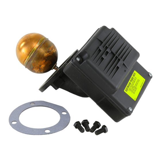
Replacement Head Mechanism
42S-HD
(Snap Switch)
Replacement head mechanisms can be installed without
disturbing existing equalizing connections or disassembly
of components, making repairs simple and easy.
• Before using this product read and understand instructions.
TI O N
C A U
N IN G
W A R
• Save these instructions for future reference.
• All work must be performed by qualified personnel trained in the proper application, instal-
lation, and maintenance of plumbing, steam, and electrical equipment and/or systems in
accordance with all applicable codes and ordinances.
• To prevent serious burns, the boiler must be cooled to 80˚F (27˚C) and the pressure must be
0 psi (0 bar) before servicing.
• To prevent electrical shock, turn off the electrical power before making electrical connections.
• This low water cut-off must be installed in series with all other limit and operating controls
installed on the boiler. After installation, check for proper operation of all of the limit and
operating controls, before leaving the site.
• To prevent serious personal injury from steam blow down, connect a drain pipe to the
control opening to avoid exposure to steam discharge.
• To prevent a fire, do not use this low water cut-off to switch currents over 7.4A, 1/3 Hp at
120 VAC or 3.7A, 1/3 Hp at 240 VAC, unless a starter or relay is used in conjunction with it.
Failure to follow this warning could cause property damage, personal injury or death.
!
WARNING
INSTRUCTION MANUAL
Replacement Head Mechanism
MM-243D
Advertisement
Table of Contents

Related Manuals for Xylem McDonnell & Miller MM-243D


Summary of Contents for Xylem McDonnell & Miller MM-243D
- Page 1 INSTRUCTION MANUAL MM-243D Replacement Head Mechanism 42S-HD (Snap Switch) Replacement head mechanisms can be installed without disturbing existing equalizing connections or disassembly of components, making repairs simple and easy. Replacement Head Mechanism WARNING • Before using this product read and understand instructions. TI O N C A U N IN G...
- Page 2 OPERATION Maximum Pressure: 50 psi (3.5 kg/cm Electrical Ratings Pump Circuit Rating (Amperes) Motor Horsepower Voltage Voltage Full Load Locked Rotor Pilot Duty 120 VAC 44.4 345 VA at 120 VAC 120 or 240 VAC 240 VAC 22.2 240 VAC Settings and Differential Pressures Values are ±...
- Page 3 INSTALLATION – TOOLS NEEDED: One (1) pipe wrench, one (1) flathead screwdriver, one (1) scraper, and one (1) 9/16" socket or wrench. STEP 1 - Preparation WARNING • To prevent serious burns, the boiler must be cooled to 80˚F (27˚C) and the pressure must be 0 psi (0 bar) before servicing.
- Page 4 STEP 2 - Installing the Replacement Head Mechanism a. Carefully remove the new replacement head mechanism from the carton. Handle it carefully to prevent damage to the float rod (G). b. Align the bolt holes of the new head gasket (H) on the sealing surface (F) of the control body.
- Page 5 STEP 3 - Electrical Wiring WARNING • To prevent electrical shock, turn off the electrical power before making electrical connections. • This low water cut-off must be installed in series with all other limit and operating controls installed on the boiler.
- Page 6 WIRING DIAGRAMS Low Water Cut-Off Only 1. Main Line Switch - For burner circuits within the 2. Pilot Switch - To holding coil of a starter when switch’s electrical rating. the burner circuit exceeds the switch’s electrical rating. LINE LINE LOAD LOAD Pump Control Only...
- Page 7 STEP 4 - Testing This control is factory calibrated for specific applica- Dimensions provided are typical for a boiler not being tions. The following testing procedure is only meant fired and/or not at pressure. Actual operating ranges to serve as a verification of proper operating are shown on page 2 in the "Operation"...
- Page 8 8200 N. Austin Avenue Valve #2 Morton Grove, Illinois 60053 Phone: (847) 966-3700 Fax: (847) 965-8379 www.xyleminc.com/brands/mcdonnellmiller McDonnell & Miller is a trademark of Xylem Inc. or one of its subsidiaries. © 2012 Xylem Inc. MM-243D December 2012 Part No. 210428...
Need help?
Do you have a question about the McDonnell & Miller MM-243D and is the answer not in the manual?
Questions and answers