
Related Manuals for KiloVault HAB SCHNEIDER XW PRO UL9540


Summary of Contents for KiloVault HAB SCHNEIDER XW PRO UL9540
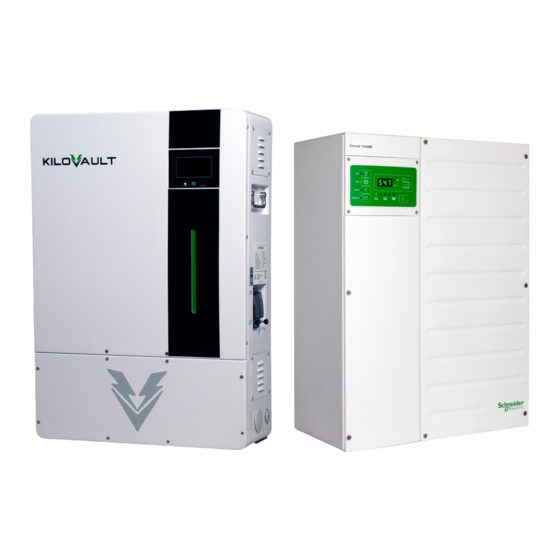
- Page 1 KiloVault® HAB™ - SCHNEIDER XW PRO UL9540 Base Kit INSTALLATION & INTEGRATION GUIDE JUNE 2022 / Rev: 1.0...
- Page 2 Additionally, the illustrations in this manual are for demonstration only and are intended to help explain the KiloVault® HAB™ system concepts and installation instructions. Details may vary slightly depending upon the market region and the product version.
-
Page 3: Table Of Contents
5.1.1. KiloVault® HAB™ Control Panel Details ..............32 5.2. Calibrating Your KiloVault® HAB™.................. 33 5.3. Charging Settings ......................33 5.3.1. Firmware Updates ......................36 5.4. Starting the KiloVault® HAB™ for the first time ............... 37 5.5. Monitoring ........................38 5.6. Maintenance ........................38 5.7. Disposal ........................... 38 6. - Page 4 20.1 Basic Functional Test - Multiple Inverters ..............49 21.1 Schneider XW-Pro Specifications..................49 WARNINIG The KiloVault® HAB™ or Conext XW Pro inverter are not intended for use in connection with life support systems or other medical equipment or devices. Failure to follow these instructions can result in death, serious injury, or equipment damage.
- Page 5 Intertek Testing Laboratories Volts Alternating Current Volts Direct Current "DO NOT DISCARD CRATE AND INTERNAL PACKAGING." Congratulations on your KiloVault® product purchase. Product registration is required for warranty coverage and allows for easier customer and technical support. https:/ /kilovault.com/register/ “VERIFY that your HAB firmware is Up To Date”...
-
Page 6: Safety Information
Install the KiloVault® HAB™ out of the reach of children and animals. Warning: The KiloVault® HAB™ is heavy, over 230 lb. (105 kg), and may cause serious back injury. Lift with multiple people and lifting equipment rated to lift and support at least 230 lb. -
Page 7: General Safety Precautions And Instructions
Install the KiloVault® HAB™ out of the reach of children and animals. Warning: The KiloVault® HAB™ is heavy, over 230 lb (105 kg), and may cause serious back injury. Lift with multiple people and lifting equipment rated to lift and support at least 230 lb. -
Page 8: Battery Handling Guide
• Verify that all equipment that is going to be connected to the KiloVault® HAB™ is turned off before making any connections. • A small risk of spark does exist while making connections. Ensure the area is free of explo- sive gasses and liquids and is not installed in confined areas. -
Page 9: Response To Emergency Situations
1.3.3. Response to Emergency Situations The HAB™ is comprised of multiple batteries and is designed to prevent hazards resulting from failures; however, no battery system is 100% safe, and KiloVault®, LLC cannot guarantee its absolute safety. In the unlikely event of a fire first shut off the source of the electricity if possible. We recom- mend a fire extinguisher in close proximity of your power generating equipment. -
Page 10: Overview
Warning: Never connect HAB™ units in series! KiloVault® HAB™ Series wall-mount energy storage systems provide a 7.5 Kilowatt-hour (7 kilowatt-hour usable) battery in a single package. Up to 14 units can be connected in parallel for additional capacity. The HAB™ Series has been designed for trouble-free mounting and is easy to connect with other system components. -
Page 11: Specifications
3. Specifications 3.1. Electrical Specifications Note: • Specifications are subject to change without prior notice. • The following are specifications only, NOT set points. The following specifications describe the HAB™ system. Item Specification Battery Type LiFePO4 Internal Resistance ≤15mΩ JUNE 2022 / Rev: 1.0 2022... - Page 12 Item Specification Battery Efficiency 94.5% Direct current Fully Charged Resting Voltage 53.6 V Full Charge Voltage 56 V RJ45 120 Ω Resistor Plug, 6-position, 4-conductor, HAB™ to HAB™ male connectors both ends. Straight through. Maxi- (inter-battery) communication cable mum length, 10 feet HAB™...
-
Page 13: Operating Environment Specifications
Recommended Floating Charge Voltage 52.8 V ≤3% per month, ≤15% per year • Note: This rate is only achieved when the KiloVault® HAB™ is put to sleep by pressing Self-Discharge Rate down the Power button for 3 seconds. • The KiloVault® HAB™ will automatically shut down after 15 minutes of no activity. -
Page 14: Physical Specifications
3.3. Physical Specifications Item Specification 230 lb (105 kg) net KiloVault® HAB™ Weight 286 lb (130 kg) gross KiloVault® HAB™ Height 32 in (812.8 mm) KiloVault® HAB™ Width 22.5 in (571.5 mm) KiloVault® HAB™ Depth 9.2 in (233.7 mm) Mounting Plate Height 18 in (458.1 mm) -
Page 15: Certifications
Item Specification Mounting Plate Ears 1.7 in (42.5 mm) Mounting Plate Lips 0.5 in (12.7 mm) KiloVault® HAB™ Ingress Rating - Vents Installed IP54 KiloVault® HAB™ Ingress Rating - Solid Plates IP55 Installed Battery Terminal Torque 15 Nm, 11.06 ft-lb, 132.76 in-lb Large (power) ports PG42: Approx. -
Page 16: Installation
Install the KiloVault® HAB™ out of the reach of children and animals. Warning: The KiloVault® HAB™ is heavy, over 230 lb. (105 kg), and may cause serious back injury. Lift with multiple people and lifting equipment rated to lift and support at least 230 lb. -
Page 17: Installation Flowchart
4.1 Installation Flowchart The following flowchart provides an overview of the installation process. Note: • Prior to installing your HAB™, please take pictures of the label on the left side, including the serial number, serial number barcode, QR code, and MAC address. -
Page 18: Unpacking The Kilovault® Hab
Retain all packaging material for the duration of your warranty period. 4.2.1. Package Contents The standard HAB™ packaging includes the battery unit, mounting brackets and screws, commu- nications cables, and built-in lift handles. Figure 4: Standard KiloVault® HAB™ Packaging JUNE 2022 / Rev: 1.0... - Page 19 JUNE 2022 / Rev: 1.0 2022...
-
Page 20: Tools, Materials, And Safety Equipment Required For Installation
• Various sized Phillips and flathead screwdrivers • Torque wrench and sockets • 1/0 battery to inverter cables • Battery combiner box (when more than one KiloVault® HAB™ batteries are being used) • Level • Pencil or marker JUNE 2022 / Rev: 1.0... -
Page 21: Suitable Installation Locations
4.4. Suitable Installation Locations The HAB™ should be installed high enough above the floor to allow the battery cables to bend without kinking and allow easy access to the knockouts on the bottom of the HAB™ . There should be about 8 inches (approx. 200 mm) of clearance on both sides. Observe the following: •... -
Page 22: Install The Kilovault® Hab™ Wall Mounting Plate
4.5. Install the HAB™ Wall Mounting Plate The HAB™ comes with the single mounting plate option. JUNE 2022 / Rev: 1.0... - Page 23 The HAB™ mounting plate can be used as a template to mark your pilot holes on the mounting surface. Choose holes so that you can mount the plate using at least four of the widely spaced holes. Use a level to ensure that the plate is level. Refer to Section 4.5.1 Mounting Surface for information regarding mounting surface requirements.
-
Page 24: Mounting Surface
Failing to wait at least 30 seconds risks causing internal short cir- cuit events and causing damage to its internal resistors. Warning: The KiloVault® HAB™ is for use with 48 V systems only. DO NOT connect them in series! JUNE 2022 / Rev: 1.0... -
Page 25: Connecting The Kilovault® Hab™ To Your Inverter
4.6. Connecting the HAB™ to Your Inverter There are access ports on the bottom left, bottom right, and on the bottom of the wiring access panel. One large and two small strain reliefs are included in the HAB™ packaging. To use them remove the plugs from the relevant access ports and replace them with the included strain reliefs. - Page 26 Failure to follow these instructions can result in death, serious injury, or equipment damage. Protective (grounding) conductor terminal KiloVault® HAB™ is provided with ground terminals that must be reliably connected to ground (protective earth) by appropriately sized equipment grounding conductors. System grounding for the AC and DC systems must be done according to all applicable NEC and local installation codes.
-
Page 27: Connecting The Kilovault® Hab
RJ45 cable. (10’ Max length) Optional: Connect the Modbus communication cable between the Leader HAB™ and the inverter. Contact KiloVault® for a list of supported inverters. Connect the power cables from the HAB™ to the inverter (or to the DC bus if installing to multiple units), making sure to use overcurrent protection as required. -
Page 28: Disconnecting The Kilovault® Hab
4.6.3. RJ45 120 Ω Resistor Plug Installation A clear RJ45 120 Ω Resistor Plug resistor plug is enclosed in each KiloVault® HAB™ unit. Plug one end into the first and last units in the string as shown. -
Page 29: Single Inverter Simplified Wiring Diagram
Ω ResistorPlug Ω ResistorPlug 4.6.4. Single Inverter Simplified Wiring Diagram These diagrams may not exactly match your specific system and may not include all the safety equipment required by regional authority. This is purely a graphical representation. It is extremely important to make all conductors to each battery the same length to help ensure they contribute balanced current. -
Page 30: Multiple Inverter Simplified Wiring Diagram
4.6.5. Multiple Inverter Simplified Wiring Diagram The following diagram describes a simplified multiple inverter system for installations greater than 7.5kW. This is purely a graphical representation. Ω ResistorPlug Wires G/L3/L2/L1/N in the previous diagram refer to the wires in a standard 3-phase system. Different inverters may have different wiring. -
Page 31: Setting The Kilovault® Hab™ Address
4.6.7. Setting the KiloVault® HAB™ Address • If your HAB™ serial number is below MWT2020010902014, please contact KiloVault® for addressing instructions. • If you are installing a single HAB™ to be used by itself, the address must be set to (off off off off). -
Page 32: Hab To Hab And Hab To Inverter Communication Cable Pin Definitions
4.6.8. HAB to HAB and HAB to Inverter Communication Cable Pin Definitions The provided inter-KiloVault® HAB™ Can-Bus communication cable is a standard, straight thru RJ45 comm cable. The provided battery to inverter Modbus communication is a custom RJ485 (non-standard). Warning: Do not plug the HAB to Inverter Modbus cable into the CAN Bus port. -
Page 33: Operation, Maintenance & Monitoring
Inverter RS485A BMS debug RS485A BMS debug RS485B 5. Operation, Maintenance & Monitoring 5.1. HAB™ Control Panel The KiloVault® HAB™ control panel displays a variety of useful information regarding the operation of your system. JUNE 2022 / Rev: 1.0 2022... - Page 34 5.1.1. HAB™ Control Panel Details Display Description Notes Battery Voltage Remaining Energy Negative value = Discharging Charge / Discharge Power Positive Value = Charging State of Charge Approximate Percentage Full Number of Cycles Battery Temperature • Off = Not connected to router. The HAB™...
-
Page 35: Calibrating Your Kilovault® Hab
5.2. Calibrating Your HAB™ Calibrate the State of Charge calculator and kWh using the following procedure. • Fully charge the battery to 56V. o If a high voltage alarm occurs, you can ignore it. You will still be below the high voltage protection. - Page 36 Under2 minutes 6 minutes, please contact KiloVault for additional information) Battery Capacity 150 Ah (7.5 kW) per KiloVault® HAB™ Lithium Ion or Custom - whichever provides access to the re- Battery Type quired settings Absorption Bulk (98% to 100% of...
- Page 37 Under 40A 40-60A 60-150A Device Setting Charger Charger Charger Absorb Time Under 6 min Under 4 min Under 2 min Absorb Voltage 56 V Battery Capacity 150 Ah (7.5 kWh) per HAB™ Do not use an external battery temperature sensor with these Battery Temperature batteries.
-
Page 38: Firmware Updates
• On the HAB™ iT Basic screen flip the slider-like switch highlighted in blue shown in Figure 20: KiloVault® HAB™ iT Basic Screen Slider Switch. The status should change to “No charge or discharge.” Figure 20: HAB™ iT Basic Screen Slider Switch •... - Page 39 If there are no alarms, the green RUN LED will be lit, and the control panel will be populated with information about the running condition of your HAB™. The control panel will remain lit for 5 minutes and then go blank. If you briefly (less than three seconds) press the HAB™ unit’s power button, the control panel will again light for 1 minutes.
-
Page 40: Monitoring
10 or above. The Android app requires Android 5.0 (Lollypop) and above. The apps are avail- able from the iOS App Store or the Google Play Store. Please see the KiloVault® website to down- load detailed HAB™ iT instructions. - Page 41 Alarm / Protection Condition Trigger Values High Voltage Alarm for each Cell 3.55±0.03 V High Voltage protection for each cell 3.65±0.03 V, Delay time: 1s High Voltage release for each cell 3.40±0.03 V High Voltage alarm for total voltage 56.6 V±0.5 V High Voltage protection for total voltage 60.0 V±0.5 V, Delay time: 1s High Voltage release for total voltage...
- Page 42 Alarm / Protection Condition Trigger Values Over current release method Auto release after 1min Charge High Temperature alarm 122°F ± 5.4°F (50°C ± 3°C) Charge High Temperature protection 131°F ±5.4°F (55°C ± 3°C) Charge High Temperature release 113°F ±5.4°F (45°C ± 3°C) Discharge High Temperature alarm 140°F ±5.4°F (60°C ±...
-
Page 43: Warning / Alarm Indicators
6.2. Warning / Alarm Indicators Display Description Required Action Battery High Voltage Reduce the charging voltage or stop charging Stop discharging the battery. Recharge within 15 Battery Low Voltage days. Battery High Stop discharging the battery. Recharge within 15 Temperature days. -
Page 44: Parallel Alarm Conditions And Connection Test
LED’s are lit Repeated. More HAB™ units con- After setting the and all the alarm than one KiloVault® nected in parallel. correct address, LED’s are flashing HAB™ has been restart the HAB™ set as the Leader. - Page 45 ALARM All units with simi- are lit. Leader RUN tor Plug. Restart LEDs have lost lar voltages. Only LED is ON. Follow- each KiloVault® communication with Leader discharg- er RUN LEDs are HAB™ using the the Leader. ing.
-
Page 46: Resetting The Kilovault® Hab
6.6. Low HAB™ voltage when unboxed If, when you turn on your KiloVault® HAB™ , you measure a very low voltage (under 40 V) at the battery terminals, it is in Low Voltage Hibernation. Press the front power button for three seconds to turn the KiloVault®... -
Page 47: Xw Pro Installation
Keep unqualified personnel away from batteries. No responsibility is assumed by Schneider Electric or KiloVault® for any conse- quences arising out of the use of this material. For information about operating the Conext XW Pro Inverter/Charger, see the Conext XW Pro Inverter/Charger Owner’ s Guide (975-0240-01-01). -
Page 48: Conext Xw Pro Features
Battery Temperature Sensor The Battery Temperature Sensor (BTS) included in this package: DO NOT USE WITH KiloVault® HAB™. Conext XW Pro Jumpers (For Single-Phase Conversion) Single phase conversion is only for 3-ph configuration (1 or 2 inverters per phase). Stacked 120V systems is not supported. -
Page 49: Single Xw Pro With Single Leader Kilovault® Hab™ (Split-Phase And Single-Phase) With Ac Coupling
9.2 Single XW Pro with Single LEADER KiloVault® HAB™ (Split-Phase and Single-Phase) with AC Coupling The XW Pro with KiloVault® HAB™ can be used with AC coupled PV inverters or microinverters. The XW Pro will regulate charging from the AC coupled PV inverters using frequency shifting, based on the battery charging limits and SOC information communicated by the BMS. -
Page 50: Fcc Information To The User
10. FCC Information to the User This equipment has been tested and found to comply with the limits for a Class B digital device, pursuant to part 15 of the FCC Rules. These limits are designed to provide reasonable protection against harmful interference in a residential installation. -
Page 51: Clearance Requirements
12.1 Clearance Requirements Provide at least 91 cm (36 in.) of clearance in front of the inverter, and a minimum of 15 cm (6 in.) of clearance at the top and bottom of the inverter for ventilation. Ensure the vents remain unobstructed, and that the Conext XW Pro Power Distribution Panel door has adequate room to fully open. -
Page 52: Ac Connections
NOTICE RISK OF BATTERY AND INVERTER DAMAGE Always follow the recommended start-up sequence and minimum batter- ies. This is required to avoid excessive in rush current. Failure to follow these instructions can result in equipment damage Single XW Pro with Single Master BMS (Split-Phase and Single-Phase) with AC Coupling 13.1 AC Connections This section provides instructions for making AC connections between the Conext XW Pro and the Power Distribution Panel (PDP) (using the pre-installed AC cables in the PDP) and... -
Page 53: Grounding Ac Equipment
To access the AC terminal block, you will need to remove the AC access panel. For more infor- mation, see "Removing the AC Access Panel and PDP Internal Faceplates" on page 44 of Conext XW-PRO-NA- Installation guide. The AC terminal block includes three terminals each (L1, L2, and Neutral) for AC Grid input (AC1), AC Generator input (AC2), and AC Out (AC LOAD) connections, see Figure below. - Page 54 Multi-Unit Power System can be used as a grid-tie power backup equipment or as primary power sources for off-grid sites. They may or may not have solar energy harvest capability or other alter- nate energy sources. Electrically, all the power devices are connected to a common AC and DC bus using appropriate circuit breakers, electrical panels, combiner boxes and/or power distribution panels (PDP).
-
Page 55: Xw Pro Multi-Unit Design Guide
14.1 XW Pro Multi-unit Design Guide Multi-Unit Power System This section provides instructions for making AC and DC connections between multiple Conext XW Pro units and a Power Distribution Panel (PDP), using the cables that are included with each PDPand Connection Kit for INV2 INV3 PDP. A Multi-Unit Power System is a group of battery-based XW Pro inverter/chargers and related devices which are physically assembled together, electrically connected together, and configured to operate as a single power source. -
Page 56: Making Dc Connections
15.1 Making DC Connections Note: Before connecting the DC cables from the PDP to the battery, perform the procedures in "Making AC Connections" To connect the Power Distribution Panel (PDP) to the Conext XW Pro: 1. Connect the positive battery cable (pre-installed in the PDP) to the positive battery terminal at the bottom of the Conext XW Pro, as shown in Figure below. -
Page 57: Battery Cable Requirements
16.1 Battery Cable Requirements Cable runs should be kept as short as practical. Length should not exceed 10 feet. Run the positive and negative cables alongside each other. Avoid cable loops. In order to keep the battery cable length short, install the Conext XW Pro as close as possible to the battery room or battery enclosure. -
Page 58: Dc Wiring For A Dual-Inverter System
To connect the PDP to the Battery Bank: Connect your battery cables (not included) to the PDP. Connect the negative battery cable to the DC Negative Bus, and the positive battery cable to the input end of the GJ250A 160 VDC, 3/8" stud DC breaker (pre-installed in the PDP), as shown in Figure LEGEND 1. - Page 59 DC Connections to Dual Inverter 2. Connect the positive battery cable for INV2 (included with the Connection Kit for INV2 INV3 PDP) to the top terminal on the second DC disconnect/breaker. 3. Connect the negative battery cable for INV2 (included with the Connection Kit for INV2 INV3 PDP) to the DC Negative Bus.
- Page 60 You will need to use the HAB iT app to set the HAB to the XW Pro communication protocol. Con- nect your HAB to the HAB iT app and use it to connect your HAB to the internet to make sure it is updated to the most recent firmware.
- Page 61 That brings you to this page. Towards the bottom right side of the screen you can see inverter pro- tocol setting .Choose 0001 to select the Schnieder XW PRO protocol. Choose 0001 to select the Schnieder XW PRO protocol. 3. Start your XW Pro (Refer To Page 67 of this Manual) 4.
- Page 62 V1, V2 & Early V3 HABs - HAB to Inverter Amphenol AT06 6S Modbus Cable. • Early V1 HABs cannot be updated through the cloud. Contact KiloVault for a kit to update the HABs locally using a personal computer. •...
-
Page 63: Wiring Interface
18.1 Wiring Interface WARNING XANBUS SHOCK HAZARD Xanbus cables in contact with DC or AC power can transmit an electric shock. Do not route the Xanbus cables in the same conduit or panel as the AC and DC power cabling. Failure to follow these instructions can result in death, serious injury, or equipment damage. - Page 64 The HAB to Inverter cable shipped with the later V3 and V4 HABs has RJ485 connectors on both ends. The ends are identical. RS485 Modbus Connector Wire Color ModBus Definition (may be different than what it says below) RS485 (Inverter Comms) white/orange RS485A (Inverter Comms) orange...
- Page 65 Steps 1. If you have more than one HAB, connect them using the HAB-to-HAB communication cable. Please see the HAB user manual for details. a.If you have a mixture of HAB versions in your battery bank, make the newest ver sion HAB the Leader.
- Page 66 4. Make sure that the rest of the Xanbus devices in your system are connected to the Xanbus net work. 5.Follow the instructions in the Insight Home manual to connect your computer to the Insight Home’s WiFi access point and log in to Insight Local (the Insight Home, Insight Facility or Gateway internal web application) using the Admin user and password 6.In InsightLocal.
- Page 67 The HAB shows up as “SECAN_BMS_0” d.Click “Setup” in the green, top, horizontal menu. i.Click “BMS Setup” in the left-hand vertical menu. 1.Select “KiloVault HAB 7.5” as the battery type. 2.Input the number of HABs in your battery bank. 3.Click “Apply”...
- Page 68 a.Set the Device Association to “House Battery Bank 1”. Click “Apply” Select your XWPro. Go into Configuration. a.Go into the “Battery Settings” menu. Enter the total capacity of your HAB battery bank (just multiply 150 by the number of HABs in your battery bank) and “Apply”. b.
- Page 69 19.1 Applying DC Power to the Inverter To apply DC power to the inverter: 1. Before applying DC power to the inverter, measure the voltage and check polarity at all connections. Measure at the battery side of the disconnect or breaker. 2.
- Page 70 20. Basic Functional Test - Multiple Inverters The following steps will complete a basic functional test of multiple Conext XW Pros. If any test fails, please refer to the Troubleshooting section in the Owner's Guide for assistance. To perform a functional test on multiple inverters: 1.
- Page 71 16. Confirm operation of connected AC loads. Note: If oscillation occurs, perform the "XW Pro/XW Inverter/Charger Multi-Unit AC Output Volt- age Configuration and Calibration" in Appendix A of the Conext XW Pro Multi-unit Power System Design Guide (990-91373). 17. Disconnect AC LOAD breakers. 18.
- Page 72 21. Schneider XW-Pro Specifications. Specifications XW Pro Continuous Output Power (Inverter Mode @ 25°C) A. INV1 IN (Grid) (6800W) Continuous Output Power (Inverter Mode @ 40°C) B. INV2 IN (Grid) (6000W) Surge Rating (Overload for 1 minute) C. Grid bypass (1200W) Surge Rating (Overload for 30 minutes) D.
- Page 73 JUNE 2022 / Rev: 1.0...
- Page 74 KiloVault* LLC KiloVault® HAB™ Series 330 Codman Hill Road Lithium Iron Phosphate (LiFePO4) Boxborough, MA 01719 Deep Cycle Solar Batteries +1(888)218–5924 info@kilovault.com www.kilovault.com JUNE 2022 / Rev: 1.0...
Need help?
Do you have a question about the HAB SCHNEIDER XW PRO UL9540 and is the answer not in the manual?
Questions and answers