Table of Contents
Advertisement
Quick Links
400RR
Q ua dro d i c om a n d o p rog r a m m ab i le
I str uz i oni d 'u s o e d avve r te n ze
P r o g ram m a bl e c on t r o l bo a r d
Ope r at i ng i nst ru c t i o ns a n d wa r n i n gs
A rmo ir e d e c o mm a nd e p r o g r a m m a bl e
Noti c e d' e mp lo i et ave r t iss e m e n t s
P r o g ram m i er b a r e Ste u er e i nh e it
Be d i e nu ng s a nle it u ng u n d Hinwe is e
C ua dro d e ma n i o br a p ro g r a m ab le
I nstr uc c i o ne s d e u s o y a d ve r te n c ia s
Q ua dro d e c o ma nd o p r o g r a m áve l
I nstr uç ões p a ra u t i liz a çã o e a d ve r t ê n c ia s
U n i we r s a l n a c e n t r a l a s te r u jąc a
I nstr uk c ja m o nt aż u i u ż y t kowa n i a
П ро гра мм и руе м а я панель у п р ав л е н ия
Инструкции и п ре д у пр е жд е ни я
Advertisement
Table of Contents

Related Manuals for Dea 400RR


Summary of Contents for Dea 400RR
- Page 1 400RR Q ua dro d i c om a n d o p rog r a m m ab i le I str uz i oni d ’u s o e d avve r te n ze P r o g ram m a bl e c on t r o l bo a r d...
-
Page 3: Warnings Summary
WARNING Product use in abnormal conditions not foreseen by the manufacturer may generate hazardous situations; meet the conditions indicated in these instructions. WARNING DEA System reminds all users that the selection, positioning and installation of all materials and devices which make up the complete automation system, must comply with the European Directives 2006/42/CE (Machinery Directive), 2014/53/UE (RED Directive). - Page 4 WARNING Using spare parts not indicated by DEA System and/or incorrect re-assembly can create risk to people, animals and property and also damage the product. For this reason, always use only the parts indicated by DEA System and scrupulously follow all assembly instructions.
-
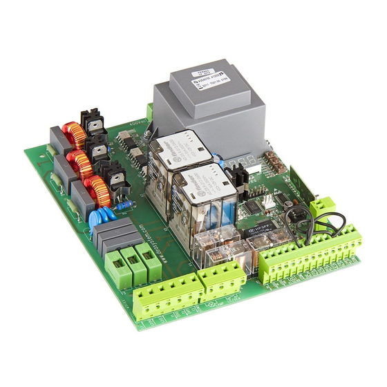
Page 5: Product Description
DEA System automatism, onto which the 400RR control board is mounted. In the case of control units supplied in a BOX, the protection rating is IP 55, if installed correctly. -
Page 6: Electrical Connections
4 ELECTRICAL CONNECTIONS Execute the wiring following the directions of “Table 1” and diagrams on page I-1. WARNING To ensure an appropriate level of electrical safety always keep the 400V 3~ power supply cables apart (minimum 4mm in the open or 1 mm through insulation) from low voltage cables (motors power supply, controls, aerial and auxiliary circuits power supply), taking care to place them in plastics ducts and fasten the latter with appropriate clamps near the terminal boards. -
Page 7: Use Instructions
5 USE INSTRUCTIONS 1 Power Supply After making all connections to the terminal board, remember to short-circuit, whenever needed, any unused input (see “connection to the control board”) and power the card: on the display you will read for a few seconds “rES-” followed by the symbol “- - - -” which stands for gate closed. - Page 8 4 Built-in radio receiver 400RR control board includes a 433,92MHz built-in radio receiver accepting both transmitters with HCS coding (complete rolling code or just fi xed part), and HT12E dip-switch coding: • The type of coding is selected by programming the working parameter P008 “type of coding” (see Parameters Table);...
- Page 9 5.2 Resetting of default parameters (P007) 400RR control board software includes a reset procedure to restore default values (the one set by the maker) of all settable parameters, see Table 2 Parameters. The value originally set for each parameter is shown in the “working parameters table”. In case you should reset...
-
Page 10: Parameter Description
PAR. PROCEDURE Positioning of gate/door Unused parameter Memorization of the motor stroke Deletion of the radio receiver memory Memorization of transmitters Search and deletion of a transmitter Resetting of default parameters PAR. PARAMETER DESCRIPTION Type of coding of the radio receiver Channel selection and linking to “start”... -
Page 11: Default Values
SETTABLE VALUES SETTABLE VALUES DEFAULT VALUES • 000: HCS fi x-code • 001: HCS rolling-code • 002: HT12E Dip-switch START START 50........100 30........100 10........50 30........100 30........100 • 000: safety ribs mode • 001: photoelectric barriers mode 0........255 0........15 • 000: deactivated •... - Page 12 Collectivity function: if it is activated it deactivates both start and pedestrian inputs for the whole duration of automatic opening and closing. Ram blow function: if it is activated, it pushes the motors close for one second before each opening movement, so as to ease the releasing of any electric lock.
- Page 13 DEFAULT VALUES • 000: deactivated • 001: activated • 000: deactivated • 001: activated • 000: inversion • 001: step-by-step • 000: photocells are activated while closing and when gate is closed • 001: photocells are always activated • 002: fotocells are activated at closing only •...
-
Page 14: Messages Shown On The Display
- If this error appears again, replace the control panel. 7 INSTALLATION TEST The testing operation is essential in order to verify the correct installation of the system. DEA System wants to summarize the proper testing of all the automation in 4 easy steps: •... - Page 15 230V ~ 400V 3~ RG58 FLASH 230V LOCK 4 x 0,5 mm 2 x 1 mm N.C. N.O.
- Page 16 Schema di collegamento con elettrofreno - Electro-brake wiring diagram - Schéma de branchement du électro-frein Anschlussschema mit Elektrobremse - Esquema de conexión electro freno - Esquema de ligações para o travão eléctrico Schemat połączenia z hamulcem elektrycznym - Схема подключения с электротормозом LC/SCA (L1) (L2)
- Page 17 Eseguire il fi ssaggio alla parete usando opportuni tasselli per viti Ø5 (non fornite); Fix the box on the wall with appro- priate bushings to anchor screws Ø5 (not included); Le fi xer au mur en utilisant des douilles à expansion pour vis adéqua- tes Ø5 (pas incluses);...
- Page 18 VISTA DA “A” Fori da eseguire sul fondo della scatola con seghe a tazza Ø37 per l’inserimento dei fermatubi; VIEW FROM “A” Holes to be drilled on the bottom of the box with a hole saw Ø37 to introduce tube fastening; VUE DE “A” Trous à percer au fond du boîtier avec une scie-cloche Ø37 afi...
- Page 19 E Mail address: deasystem@deasystem.com declare that the DoC is issued under our sole responsibility and belongs to the following product: Apparatus model/Product: 400RR – 400RR/C – 400RR/PROBOX Type: Universal control panel for 230V operators Batch: See the label on the back of the user manual...
- Page 20 BATCH DEA SYSTEM S.p.A. Via Della Tecnica, 6 - 36013 PIOVENE ROCCHETTE (VI) - ITALY tel: +39 0445 550789 - fax: +39 0445 550265 Internet: http:\\www.deasystem.com - E-mail: deasystem@deasystem.com...
Need help?
Do you have a question about the 400RR and is the answer not in the manual?
Questions and answers