
Related Manuals for Actox ABC40DC


Summary of Contents for Actox ABC40DC
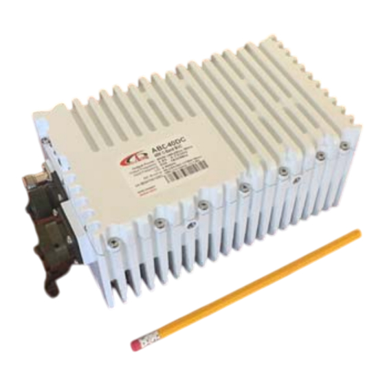
- Page 1 ABC40DC User Manual ABC40DC / ABC40DCF 40 W Extended C‐Band BUC USER MANUAL Page 1 of 34 ...
-
Page 2: Table Of Contents
ABC40DC User Manual Table of contents Introduction……………………………………………….……………..………... Receiving and …………………………………………………..…………………...….. inspection Equipment Damage or Loss Return of Equipment Preparing for …………………………………………………….…………..…….….. installation Safety Precautions General ………………………………………………..…………….……….….. description Considerations Securing the Block Up Converter Installing the Block Up Converter…………………………………………………………………………………….…………...9 LED Indicators, Connector Pin Assignment, 10MHz Reference Powering Options, Setting L.O., Setting Tx/Rx Frequencies... - Page 3 ABC40DC User Manual ………………………………………..………..………... Operation Procedure ……………………………………….…………………....Maintenance Preventive Care Procedure Block Up Converter Cooling System Preventive Maintenance Performance Check Troubleshooting Out-of Warranty Repair Appendix 1 Technical …………..………………………………….……...….….. Specifications Appendix 2 Mechanical ………………………………………….……………….…….…..…. Drawing ………………………………………………………. Appendix 3 Spare Parts …..19...
- Page 4 ABC40DC User Manual Scope This document covers the installation, operation, and maintenance of the ABC40DC BUC. It contains information intended for engineers, technicians and operators working with the block up converter. To make inquiries, or to report errors of fact or omission in this document, please contact Actox Corporation at toll free 866‐888‐6087. Page 4 of 34 ...
-
Page 5: Introduction
ABC40DC User Manual INTRODUCTION The ABC40DC is a reliable, high quality, cost efficient stand-alone block up converter. The application for this block up converter is C-Band VSAT communication in an outdoor environment. This line of superior products, engineered using state of the art technology, is characterized by unparalleled durability and dependability. -
Page 6: Receiving And Inspection
Actox Corporation Identify, in writing, the condition of the equipment, Refer to the Invoice, Purchase Order and the date the equipment was received. Notify Actox Corporation RMA department of the equipment condition and obtain a Return Material Authorization (RMA) number and shipping instructions. Do not return any equipment without an RMA number. This is important for prompt, efficient handling of the ... -
Page 7: Preparing For Installation
ABC40DC User Manual Preparing for Installation Before attempting to install or use the block up converter, we recommend that you first familiarize yourself with the product by reading through this manual. Understanding the operation of the system will reduce the possibility of incorrect installation, thereby causing damage or injury to yourself or others. The block up converter must be installed in accordance with the conditions and recommendations contained in the following sections. -
Page 8: General Description
Band. The block up converter can be used as a stand-alone unit or in a redundant configuration. Specifications Table 1 summarizes the specifications of the ABC40DC BUC. For mechanical specifications, refer to the outline drawing, Appendix 1. General Considerations The block up converter shall meet all specifications over full bandwidth and under all environmental conditions when terminated with a load of VSWR at 2:1 unless otherwise specified. -
Page 9: Installing The Block Up Converter
ABC40DC User Manual Installing the Block-Up Converter Tools and Test Equipment Have on hand a standard electrician's tool kit and any tools listed in the antenna manufacturer's installation instructions. Site Considerations The BUC is designed to mount on the antenna. Locate and install the antenna according to instructions supplied by the antenna manufacturer. - Page 10 ABC40DC User Manual LED Indication SSPA LED Green All OK SSPA LED Red Summary Alarm L.O. LED Yellow L.O. is set to 4.9 GHz NO LED indicators NO POWER 10MHz LED Green External 10MHz Reference 10MHz LED Red 10MHz is Absent 10MHz LED Green Blinking Internal 10MHz Reference 10MHz Reference The BUC must receive a stable external 10MHz reference provided by a stable signal source such as a signal generator, satellite modem or injected externally with a Bias T (for example, ABT6ARN/ABT6ARF manufactured by Actox Corporation) or a similar bias T type. Please make sure to check the sticker on the BUC for the appropriate power source before any power connections are performed. Page 10 of 34 ...
-
Page 11: Recommended Test Equipment
ABC40DC User Manual Recommended Test Equipment The following equipment or equivalent is recommended for installation and system alignment: Equipment Type Spectrum Analyzer HP8563E Digital Voltmeter Fluke 8050 Adapter Waveguide to coax C or Ku-band RF cables With calibrated insertion loss up to 15GHz 40 dB attenuator High Power to match HPA output. -
Page 12: Assembly And Installation
ABC40DC User Manual Connections and Mounting Hardware The IF input connection requires a coaxial cable with an F or N type connector. The RF output requires a waveguide with a CPR-137G flat flange. An O-ring shall be used to seal the waveguide connection. -
Page 13: Functional Overview
ABC40DC User Manual Functional Overview General This section describes the block up converter functions in detail. The functional overview explains the RF amplification, monitor & control and power distribution. IF/RF Conversion and Amplification The IF Input requires a signal with a 10MHz reference, and 36 - 60 VDC power source. 2-4.5Amps nominal enters the BUC by a coaxial cable, converted to C-Band by the BUC and goes through an internal isolator and reject filter, which provides a good VSWR at the input. -
Page 14: Operation Procedure
ABC40DC User Manual Operation It shall be performed by authorized personnel prior to maintenance and/or repair. Procedure Verify that the installation procedure described was completed. A complete physical check of the customer’s system is suggested. The output power available at the output waveguide flange is extremely hazardous. -
Page 15: Maintenance
ABC40DC User Manual Maintenance This section contains information on how to maintain, troubleshoot and repair the block up converter. The block up converter is extremely reliable, requiring very little preventive maintenance, or repair. Should there be a malfunction, this section also contains technical information to help diagnose basic failures. -
Page 16: Performance Check
Corporation after RMA number has been issued. A non-warranty and out-of-warranty repair service is available from Actox Corporation for a nominal charge. The customer is responsible for paying the cost of shipping the BUC both to and from Actox Corporation for these repairs. ... -
Page 17: Appendix 1 Technical Specifications
ABC40DC User Manual Appendix 1 TECHNICAL SPECIFICATIONS RF frequency 5.850 to 6.725 GHz Local oscillator 4.90 GHz IF frequency 950 to 1,825 MHz Output power 40W typ. (+46 dBm min.) IF connector N-type or F-type (field-exchangeable) Power supply : auto-ranging via MS connector... -
Page 18: Appendix 2 Mechanical Drawing
ABC40DC User Manual Appendix 2 Mechanical Drawing Page 18 of 34 ... -
Page 19: Appendix 3 Spare Parts
Email: mark_moore@actox.com For additional information, please contact our customer service department at: (619)906-8893 or 1-866-888-6087 Actox Corporation designers and manufacturers of telecom & wireless products Spare Parts Order Form ABC40DC Ext. C-Band BUC From: Place By: Signature: Telephone: Email: Part Description... -
Page 20: Appendix 4 M&C Commands
ABC40DC User Manual Appendix 4 M&C Commands Reply Packet format Explanation Interpretation Examples ACK (Acknowledge 7E FX E0 ZZ 7F Acknowledge that the X = Device address of the packet 1) reply: 7E FF E0 E0 7F received packet was source device. (ACK reply sent from properly processed. ZZ = CRC. the BUC) NACK (Not Acknowledge) 7E FX F1 YY ZZ 7F Indicate that a X = Device address of the packet 1) reply: 7E FF F1 03 F2 problem was source device. 7F encountered with YY = Error code (NACK reply sent from the received packet. (03 = Incorrect CRC the BUC for an 18 = Unrecognized command ... - Page 21 ABC40DC User Manual 7E FF 84 18 FF 01 F9 F7 7F (Gain = 0x01F9 = 0d505 = 50.5dB.) 1) cmd: 7E FF 02 18 FE E4 reply: 7E FF 84 18 FE 00 C8 AA 7F 7E FF 02...
- Page 22 ABC40DC User Manual 1) cmd: 7E FF 02 00 05 07 7F reply: 7E FF 84 00 05 00 01 80 7F (Low 7E FF 02 XX = Alarm state (0 = Update low power Query device for power alarm is raised) 2) cmd: 7E...
- Page 23 ABC40DC User Manual NOTE: The packets shown are based on the assumption that the Booster device address is set to 0xF. To modify the commands for different addresses, the Dest/Src byte and the CRC byte will have to change in all packets.
- Page 24 ABC40DC User Manual CRC Calculation Example To send a command to read the temperature (database element = 0x0606) from the Booster (device address 0x0F), the command is: Example Only --------------------------------------------------------------------------------- 7E FF 02 06 06 02 7F Dest/Src = 0xFF...
-
Page 25: Appendix 5 M&C Connection Instructions
ABC40DC User Manual Appendix 5 M&C Connection Instructions BUC 19 pin connector for a PC / Laptop BUC connection to PC carried by cable with 19 pin female connector (fig.1) on the one side and RJ45 (fig. 2), two DB9 (fig. 3) female connectors: RS232 and RS485 on the other side. Figure 1.1 — 19 pin connector configuration Figure 1.2 — DB9 connector configuration Figure 1.3 — RJ45 connector configuration Page 25 of 34 ... - Page 26 ABC40DC User Manual PC interface name From PC Interface pin Pin name From BUC pin NC NC R NC NC U NC NC K Ethernet 3 RX_P C 6 RX_N P 1 TX_P L 2 TX_N N RS‐485 5 GNDISO A 4 TX_B H ...
- Page 27 ABC40DC User Manual BUC User Manual via PC Run NewBuc v.301 on your PC, when it opened you will see next window: Figure 2.1 — Start window with Monitor Tab In the head there is device information, such as: Device Name: Name that you can give to your device (You can change device name in the tab Settings) Model Number: Read only. Factory set. Presents model of your device. Operation Time: The time that was passed since BUC was switch on. Serial Number: Read only. Factory set. Each unit has a unique number. Below the head you can find two tabs: Monitor and Settings. Monitor Tab Tab Monitor provides online telemetry of BUC: Output Power: Display the output detector value in W and dBm. Internal Temp: Display the BUC Hot spot temperature in degree Celsius. Internal Voltage: Display the BUC input voltage value in volts. Current Draw: Display the BUC input current value in amperes. Gain: Display the BUC gain value in dB. Attenuation: Configurable parameter. Controls gain attenuation. For change attenuation lever (from 0 db to 20 db) fill new value in the field and click button Set to apply changes. Page 27 of 34...
- Page 28 ABC40DC User Manual MUTE: Configurable parameter. Stand‐by BUC (On/Off output transmit). Includes two modes: Mute – output transmitter will be shut down until demand; Unmute – output transmitter will be always switched. For changing mode click the button Set. 10 MHz: Configurable parameter. Allows switch reference frequency. Includes two ...
- Page 29 ABC40DC User Manual Figure 2.3 — Program Address Configurations Settings Tab Tab Settings open access to change BUC configurations. The tab indicated on the fig. 2.4 Figure 2.4 — Start window with Settings Tab Internet Connection Parameters: IP Address: Configurable. Factory default, 192.168.1.250; Default Gateway: Configurable. Factory default, 192.168.1.1; Port: Configurable. Factory default, 80; Subnet Mask: Configurable. Factory default, 255.255.255.0; MAC Address: Configurable. Factory default, 02‐00‐00‐01‐00‐02; DHCP: Configurable. Factory default, disable; BUC Address Configuration: Displays current BUC address. Button Read allows find out current address. Additional BUC Options: Page 29 of 34 ...
- Page 30 ABC40DC User Manual Device Name: Let you rename your device; Description: Write here description or notes about your device; Start Mute: Option that lets you to start BUC muted. Configurable. Factory default, disable. LED`s: Option that lets you to switch on/off LED`s on dashboard. Configurable. Factory default, enable. Ref Button: Changes button functions: o Led sw: switch on/off LED`s on dashboard; o Ref sw: switch on/off auto detect function (if BUC works on internal reference frequency ). Configurable. Factory default, Ref sw. Firmware version: Displays current version of BUC`s firmware. __________________________________________________________________ NOTE For correct work of the device program version must be equal or higher than firmware version. __________________________________________________________________ ...
- Page 31 ABC40DC User Manual BUC User Manual via Ethernet For connection with BUC via Web use internet browser. You will see next page: Figure 3.1 — Start Page For log in type your login and password in appropriate fields. There are two access levels: User and Admin. By default User`s access level ID: Login: User, Password: 1234; Admin`s access level ID: Login: Admin, Password: 1234; When you enter will be loaded next page: Figure 3.2 — Monitor Tab Page 31 of 34 ...
- Page 32 ABC40DC User Manual In the head of the page you will find information about your device (BUC Name, Model and Serial Number) and current access level (User or Admin). On the tab Monitor situated BUC telemetry and BUC Alarms. Tab Monitor is functionally similar to the tab Monitor from the program NewBuc v.301 (see fig. 2.1). This tab looks the same for all access levels. To change the settings switch on the tab Control on the tab panel. Figure 3.3 — Control Panel On this panel you can configure options from the Monitor tab. MUTE: to change mode from MUTE to UNMUTE click button Switch; 10MHZ: to change mode from INTERNAL to EXTERNAL click button Switch; L.O.: choose right Local Oscillation frequency and click button Set to apply changes; Attenuation: for change attenuation lever fill new value in the field and click button Set to apply changes; Gain: displays gain value after attenuation; This tab looks the same for all access levels. Tab Settings contains information about connection parameters and administration panel for changing user`s login and password. Tab looks different for different access levels. Tab for user and admin access levels shown on the fig. 3.4 and 3.5: Page 32 of 34 ...
- Page 33 ABC40DC User Manual Figure 3.4 — Settings Panel (Access Level: User) This tab conditionally divided into two panels. Left panel contains information about current connection parameters (DHCP status, IP Address, Subnet Mask, Default Gateway, Port and MAC Address), connection speed (for RS232 and RS485 ports) and BUC address. Right panel designed to change login configurations, such as Name and Password. Figure 3.5 — Settings Panel (Access Level: Admin) Admin Access level gives wider range of configurations. In this access level available several new parameters, such as: Page 33 of 34 ...
- Page 34 ABC40DC User Manual DHCP: you can switch on/off DHCP; SMNP Manager IP: set IP address of the computer that will receive Traps from your device. The Trap is data package that consist reports about crushes in BUC. Traps are received by SNMP browser. As a SNMP browser recommended to use ...
Need help?
Do you have a question about the ABC40DC and is the answer not in the manual?
Questions and answers