Lincoln Electric TORCHMATE 4400 User Manual
Hide thumbs
Also See for TORCHMATE 4400:
- User manual (56 pages) ,
- Site prep manual (12 pages) ,
- Replacing manual (23 pages)

Related Manuals for Lincoln Electric TORCHMATE 4400


Summary of Contents for Lincoln Electric TORCHMATE 4400
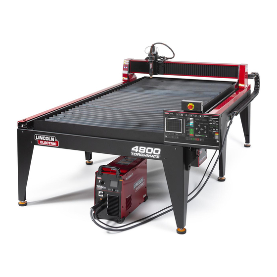
- Page 1 TORCHMATE® 4400 | 4800 | 4510 USER GUIDE October 12, 2021 Copyright 2021 Lincoln Electric® Cutting Systems...
-
Page 3: Table Of Contents
Table of Contents Unpacking Your New Machine ..............v Technical Support | On-Site Service ............vi Safety Information ..................1 Machine Specifications ................8 Site Preparation ....................9 Grounding Your Machine ................10 Power/Air/Water Requirements ............... 11 FlexCut 80 Plasma Controls & Settings ...........12 FlexCut 125 Plasma Controls & Settings ..........14 Powering Up the Torchmate 4x00 ............ -
Page 4: Unpacking Your New Machine
Verify all items have been shipped without damage before you accept the order from the shipping company. Notify Lincoln Electric® 775-673-2200 to report any shipping damages. Your machine was fully tested at the factory and a cut metal sample can be found in the waterbed of the machine. -
Page 5: Technical Support | On-Site Service
Technical Support | On-Site Service Lincoln Electric Cutting Systems provides a number of technical support opportunities with the purchase of your new 4400, 4800, or 4510 Torchmate CNC cutting machine. The following is a brief outline of available options. Onsite visits are available at an additional cost, call 775-673-2200 for additional information. -
Page 6: Safety Information
Safety Information Torchmate and Lincoln Electric Cutting Systems equipment is designed and built with safety in mind. However, your overall safety can be increased by proper installation and thoughtful operation. WARNING: DO NOT INSTALL, OPERATE, OR REPAIR THIS EQUIPMENT WITHOUT READING THE SAFETY WARNINGS CONTAINED THROUGHOUT THIS MANUAL. - Page 7 FUMES AND GASES can be dangerous: Plasma cutting or gouging may produce fumes and gases hazardous to health. Avoid breathing these fumes and gases. When cutting or gouging, keep your head out of the fumes. Use adequate ventilation and/or exhaust at the arc to keep fumes and gases away from the breathing zone. Use an air-supplied respirator if ventilation is not adequate to remove all fumes and gases.
- Page 8 Cutting flame and sparks can cause FIRE OR EXPLOSION: • Fire and explosion can be caused by hot slag, sparks, oxygen fueled cutting flame, or the plasma arc. • Have a fire extinguisher readily available. Provide a fire watch when working in an area where fire hazards may exist.
- Page 9 ARC RAYS CAN BURN: • Plasma Arc Rays can injure your eyes and burn your skin. The plasma arc process produces very bright ultraviolet and infrared rays, which will damage your eyes and burn your skin if you are not properly protected.
- Page 10 AUTOMATIC OPERATION: • Any computer numerical control (CNC) machine may begin to operate automatically without warning. Only a trained individual familiar with the software, machine, and computer system should operate this equipment. • All untrained persons should not work on or near a CNC machine. •...
- Page 11 PUBLICATIONS Refer to the most recent versions of the following standards for more information: • OSHA, SAFETY AND HEALTH STANDARDS, 29CFR 1910, obtainable from the Superintendent of Documents, U.S. Government Printing Office, Washington, D.C. • ANSI Standard Z49.1, SAFETY IN WELDING AND CUTTING, obtainable from the American Welding Society, 8669 NW 36 Street, #130;...
-
Page 12: Machine Specifications
Machine Specifications TORCHMATE CNC PLASMA SYSTEMS SPECIFICATIONS TABLE DIMENSIONS 4400 74” x 67” x 63” 4800 74” x 114” x 63” 4510 86” x 138” x 63” MACHINE WEIGHT W/O WATER 4400 840 lbs 4800 1252 lbs 4510 1595 lbs Water Capacity 4400 60 gal... -
Page 13: Site Preparation
Site Preparation When installing a Lincoln Electric CNC Cutting System in your shop, there are many factors that will influence the potential productivity, ease of use of the machine and the safety of the operator. The main factors to prepare for include: the physical layout and placement of the machine in the shop, the availability of power, an EMI ground, compressed air and other gasses, and ventilation. -
Page 14: Grounding Your Machine
Grounding Your Machine The 4x00 machines require an earth ground rod to ensure personnel safety, and to supress the high-frequency noise created by the plasma power supply. A star ground point on the table will connect directly to the earth ground rod via a 6 AWG stranded wire or other stranded, grounding cable. -
Page 15: Power/Air/Water Requirements
Water should be installed in the table pan before operation. Rust inhibitors such as non-sodium nitrite based products may be used as a corrosion inhibitor in CNC plasma water tables. Operators are encouraged to use Lincoln Electric® PlateGuard PlateGuard is mixed at a 10:1 ratio with water. Visit www.torchmatestore.com... -
Page 16: Flexcut 80 Plasma Controls & Settings
FlexCut 80 Plasma Controls & Settings Please refer to the complete operation and user manual for your FlexCut 80 located with the plasma unit. When the Machine is turned on, and auto-test is executed, all of the LEDs on the Control Panel will light up. Controls »... - Page 17 FlexCut 80 Plasma Controls & Settings Please refer to the FlexCut operators manual for complete installation and operation guidelines. Do not overtighten the consumables. Only tighten until the parts are seated properly. Rated Output: Product Product Input Power Current/ Input Current @ Output Gas Pressure Gas Flow...
-
Page 18: Flexcut 125 Plasma Controls & Settings
FlexCut 125 Plasma Controls & Settings Please refer to the complete operation and user manual for your FlexCut 125 located with the plasma unit. When the Machine is turned on, and auto-test is executed, all of the LEDs on the Control Panel will light up. Controls »... - Page 19 FlexCut 125 Plasma Controls & Settings Please refer to the FlexCut operators manual for complete installation and operation guidelines. Do not overtighten the consumables. Only tighten until the parts are seated properly. Rated Output: Product Product Input Power Current/ Input Current @ Output Gas Pressure Gas Flow...
-
Page 20: Powering Up The Torchmate 4X00
‘HOME’ position. Your machine is now prepared and ready to run. Lower Left Corner To power down the Torchmate 4400/4800/4510 CNC machine, please follow the instructions below. Step 1: Press SHUTDOWN. A prompt will display “Turn Off the Accumove Controller before pressing OK”. Press on the E-STOP button to Step 2: power down the controller. -
Page 21: Overview Of The Visual Machine Designer
Overview of the Visual Machine Designer Visual Machine Designer (VMD) is the driver software to all ACCUMOVE® CNC controllers. This design allows the operator to access a majority of the table's controls from the main screen, while hosting other features that aid in creating and manipulating files. -
Page 22: Job Group
Job Group The Job Group covers any “job” type functions. This group directly deals with selecting a job, creating a job (Shape Library), Nesting, and other Job type functions. Select Job: Allows the operator to choose the job which they would like to load. The SELECT JOB folder shows the “HOT FOLDER”... - Page 23 Job Group: Process Stations: Configure and control the tool outputs on the machine. • Kerf - Add a Kerf value to compinsate for the tool kerf value. • Set Offset - Capture the distance based on the torch position to a Plate Origin •...
-
Page 24: View Screen
View Screen The main view screen of the VMD hosts tabs that control and display the job and the corresponding settings for cutting the material. The tabs at the top of the screen gives the operator different views and controls for the job planning to be cut. Process Setup: The process setup tab is used to enter the material you are planning to cut. - Page 25 View Screen: Graphics View: The machine limits are displayed in blue. The head is represented with white crossed lines. • Plasma assigned tool paths are displayed in red. • Plate Marker assigned tool paths are displayed in green. • Rapid travels will be a dashed grey line. •...
-
Page 26: Datum & Program Zero Group
Run Group The Run group controls the startup of the machine along with running jobs. Datum: Datum has several features. When first starting up your machine, datum will power your motors and move the machine to establish its MACHINE ZERO. Once the torch has moved to the far left corner, the machine is ready to operate. -
Page 27: Jogging
Jogging Jogging allows the user to move the head by pressing on the direction. The Jogging group has several types of jogs that can be executed, allowing the user finite control over the direction, distance, and speed the head will move. Jog: The JOG keys are assigned to the movement of torch to the origin of the operators console. -
Page 28: Avhc & Dashboard
AVHC & Dashboard AVHC (Arc Voltage Height Control) hosts “how” the controllelr handles the lifter station. Dashboard gives the operator insight into the head position and other status indicators. AVHC (Automatic Voltage Height Control): Cut Parameters can be toggled between Program Defined and User Defined: •... - Page 29 AVHC & Dashboard: IHS (Initial Height Sense): This setting turns OHMIC Detection on or off: • On - The head will detect material when the ohmic cap comes into contact with the grounded, conductive material on the table. Once detected the head will retract to the transfer height setting.
-
Page 30: Accessory Toggle
Accessory Toggle The accessory panel hosts the added accessories toggle buttons. These added toggle buttons are not visible unless commissioned through the options panel. Below are the instructions to operate the laser pointer accessory. The Pipe Cutter Accessory operation will be covered in a separate document. Laser Operation: The Laser Plate Finder is intended to aid an operator at the control console to locate the approximate centerline position... -
Page 31: Using The Shape Library In Vmd
Using the Shape Library in VMD In the VMD, you can generate one of 36 standard shapes without needing to generate them in your CAD software. Access the Shape Library: To get to the Shape Library, press Shape Library located on the left hand side of the VMD screen, in the Job Group. - Page 32 Using the Shape Library: Open Shape in VMD: In the upper left of the screen, press 'Select Job'. This will open the Select a Job screen. Select the job from the list. If you didn’t save in the JOBS folder, you will need to press 'browse' and locate your job.
-
Page 33: Running A Job
Running a Job When you have a GM format file to run or shape generated in the VMD ready to cut, there is a simple process to follow to get the job produced through the VMD. This will go over the workflow of running the job. Datum: When you first start the Visual Machine Designer and are connected to the Accumove controller, the machine needs its motors powered on and machine zero... - Page 34 Running a Job: Plate Setup: Press Plate Setup. Then use the jog keys to move the torch body to the lower left corner of the material you are planning to cut. Press Set Plate Origin. This establishes the Program Zero of the program, or the absolute X 0: Y 0 of the job.
-
Page 35: Cut Quality
Cut Quality Line Speed Test: The total goal is to make sure the cuts coming off of your table are the best possible. This means that there is minimal dross accumulation on the underside of your cut parts and minimal bevel on the sides. -
Page 36: Build Your Own Cut Chart
Build Your Own Cut Chart Use this template to create your own custom cut charts using the line speed test. Material Thickness Amperage Cut Speed Pierce Delay Pierce Height Cut Height Type User Guide... -
Page 37: Nesting
Nesting VMDNesting is an irregular parts nesting program. This allows the operator to import DXF or DWG files without the need for an offline CAM software to generate the proper G-Code. The nesting will apply the kerf correction along with the appropriate lead- ins to all features. - Page 38 Item List will open along with the Nest Layout. To add parts, go to the right toolbar and press Parts. This will open the parts list. Select Import CAD Drawings for DXF/DWG files. This will bring up the Part Selector. Apply Tool Paths: At the top of the screen will be File Type, Source, and Destination.
- Page 39 Make Nest: When all the parts have the proper quantity, go to the right button list and select Nesting. Press Nest and it will display a pop up asking for All or Selected parts. Make your selection and press OK. This will then arrange your parts into the material and display the layout in the Job screen.
-
Page 40: Performing Your First Test Cut
Performing Your First Test Cut There are multiple test files pre-loaded on the computer of the Torchmate 4400/4800/4510 models for testing and cut quality purposes. The Line Speed Test and Simple Test Cut are provided to help determine the proper feed rate in IPMs to cut the material thickness to the amperage you have set on the plasma power supply. -
Page 41: Maintenance
Maintenance As with all machinery, there is required maintenance. This will cover Daily, Monthly, and ‘As Needed’ tasks to keep your 4400/4800/4510 running like new. Daily Maintenance: Plasma Power Supply: The plasma power supply and torch body will need to be evaluated between material thicknesses or prior to cutting. Remove and check if the consumables need to be changed. - Page 42 Daily Maintenance: Machine: The breakaway assembly has two magnets and three detents that should be cleaned from any collection of metallic debris, as this can cause the torch mount to be pushed far enough from the sensor for the breakaway to reliably activate.
- Page 43 Step 5: Attach the side cover to the table. PLEASE NOTE: Slide the cover so the bolts go back into their original position at the bottom of the keyhole, and torque the bolts to 17.8 in. lbs. Step 6: Repeat steps 1-5 for the other side of the table. Remove the red Gantry Side Covers by removing the four 1/8"...
- Page 44 Please Note: • The purchasers of products from Lincoln Electric Cutting Systems are responsible for disposing of consumables, fluids, and machinery at the end of the life cycle in accordance with federal and local regulations. User Guide...
-
Page 45: Cut Quality
Cut Quality Beveled edges are caused by the motion of the plasma gas as it is emitted from the nozzle. In plasma cutting, it is unavoidable. A high-definition plasma cutter produces less bevel than a standard cutter. Torch height, air pressure, air quality, cut direction, and consumable condition all influence bevel. In plasma arcs used for cutting, the gas forms into a vortex. - Page 46 How Torch Position Affects Bevel: Correct torch height: Torch angled to Incorrect torch height: Incorrect torch height: Torch square to material material Torch too high Torch too low Position of torch while cutting Bevel of finished part Equal bevel on all sides Unequal bevel Excessive bevel Reversed bevel...
- Page 47 What Causes Bad Cuts: Instances where the metal was not fully cut indicate a few problems: 1. Ground clamp is not properly attached to the material 2. Air pressure drop or surge 3. Moisture in the air line 4. Drop in power 5.
-
Page 48: Basic Troubleshooting
Basic Troubleshooting Machine Faults: Problem Solution LOG ON as ADMIN. Reload your configuration. Press OK. One motor will not engage when DATUM the DATUM machine. machine. If the issue still persists, contact Customer Support. Grease the side cassettes. If the issue still persists, contact Binding of the gantry when running parts Customer Support. - Page 49 Software Faults: Problem Solution Check to make sure the Orange Ohmic Wire is con- nected to the ohmic clip. Validate the clip is contact- ing the shield. During an Initial Height Sensing routine, the Ohmic Light does not indicate a Yellow Detected status Check that the material surface is free of rust or when the torch contacts the material.
- Page 50 Software Faults (Cont.): Problem Solution Check that the Cut height is set at the correct value. Check that the AVHC Auto/Manual mode is set to Auto. During the initial cut movement, the torch shield comes into contact with the material stopping the Check that the Sample Voltage mode is set to ON.
- Page 51 Software Faults (Cont.): Problem Solution To register the software, e-mail the support@torchmate. When VMD is opened, a Trial Period screen appears. com e-mail address with the 8 digit alpha numeric code that appears on the registration screen. Check that the breakaway capture leash and any debris on the magnet are not keeping the torch from sitting fully in position.
- Page 52 Software Faults (Cont.): Problem Solution Verify that the windows installation is using the language package English (US). Verify that the user has full administrative rights to When opening the VMD software a “Language the local computer. Deserialization Error” appears. Verify the .NET 3.5 Framework is enabled under Windows Features, both HTML Activation and Non- HTML Activation.
- Page 53 Software Faults (Cont.): Problem Solution Power down the Accumove controller and verify all motor cable connections are fully seated on the back of the Accumove controller, as well as at each motor. Power up the Accumove controller and after 30 sec- One of the machine’s motors is not moving when attempting to Datum or Jog the machine onds open the VMD software.
- Page 54 Software Faults (Cont.): Problem Solution Clear the surface of the material of any corrosion that would hinder the ohmic sensing process. Torch retracts fully to the top after sensing the Verify the torch lead is not getting pulled tight on the material in an ohmic sense, and the Run Job button way down to the surface of the material.
- Page 56 Lincoln Electric is a responsive manufacturer, but the definition of specifications, and the selection and use of specific products sold by Lincoln Electric is solely within the control of, and remains the sole responsibility of the customer. Many variables beyond the control of Lincoln Electric affect the results obtained in applying these types of fabrication methods and service requirements.
Need help?
Do you have a question about the TORCHMATE 4400 and is the answer not in the manual?
Questions and answers