Table of Contents
Advertisement
Quick Links
Advertisement
Table of Contents

Related Manuals for GGMgastro MHGGM26


Summary of Contents for GGMgastro MHGGM26
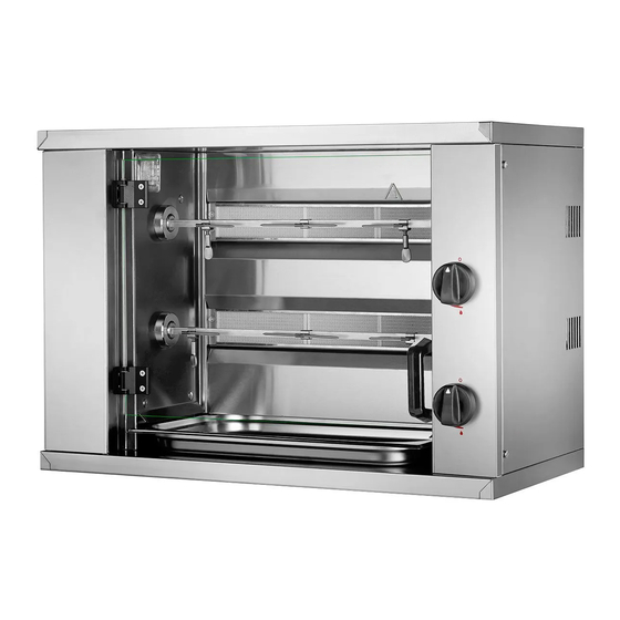
- Page 1 USER’S MANUAL MINI VERTICAL OVENS MHGGM26 MHGGM339 MHGGM412...
- Page 2 INDEX Chapter 1………. General description Chapter 2………. Apparatus’ use Chapter 3.... Loading and cleaning the oven Chapter 4………. Technical instructions for installation and adjustment Chapter 5……… Spare parts assembly Appendix A……. List of spare parts and Appendix A.1….. Electric diagrams p. 64 Appendix B……..
-
Page 3: Chapter 1 General Description
CHAPTER 1 GENERAL DESCRIPTION INDICATIONS This apparatus should be installed in compliance with legislation in force and should be used in well ventilated areas only. Read the instructions prior to installation and use. For correct combustion the place where the grill is installed must have at least minimum ventilation 10m³... -
Page 4: Chapter 2 Apparatus' Use
ACCESSORIES The oven is equipped with a series of accessories such as the spits, skewers, hook for removing the spits and tray. a) Spits Their purpose is to fix, through the skewers, the food to be roasted. Their cross-section is square so that they will rotate when placed in the drag axles. - Page 5 ORDER FOR LIGHTING Always start at the top of the oven downwards until you reach the bottom layer. WARNING: You should never leave a burner on for roasting when the one below it is off. Close the regulators and taps when the oven is not in use. ROTATION OF THE SPITS When you press the switch at the bottom left of your oven, this will light up and the spits will start to turn.
-
Page 6: Change Of Gas Type
CLEANING THE INTER-BURNER SHEET This sheet, situated between the burners, can be removed to facilitate cleaning. To do this, proceed as follows: (fig. 6). a) Pull the bottom of the sheet towards you until it is horizontal. b) Lift it until you notice that the sheet has reached a limit. c) Then pull it outwards and the sheet will have been extracted from the oven. - Page 7 CHAPTER 4 TECHNICAL INSTRUCTIONS FOR INSTALLATION AND ADJUSTMENT INSTALLATION These operations can only be carried out by a certified technician. The appliance must be placed on a flat, stable surface. This device must be installed in accordance with the regulations in force, and should be used only in well-ventilated areas. For correct combustion the place where the grill is installed must have at least a minimum ventilation 10m³...
- Page 8 CONNECT THE OVEN At the bottom right at the back of the oven you will find a ½” gas connector for ovens using Butane/Propane gas. Next to the gas inlet is the cable for connecting to the electricity mains. The hose gas supply must meet the regulations in force and it should be checked periodically and replaced when necessary.
- Page 9 MINIMUM BURNER ADJUSTMENT a) Remove the control of the valve of the burner you wish to adjust. b) Put a screwdriver through the hole in the control panel and loosen the screw (1) Fig. 8 in a clockwise direction to reduce the minimum or anticlockwise to increase the minimum. c) Replace the control once the minimum has been adjusted.
- Page 10 CHAPTER 5 ASSEMBLY OF SPARE PARTS WARNING: These operations can only be done by an authorised technician Once a year, a revision of the device must be carried out, taking into account the cleaning of the injectors and the gas outlet valves. CHANGING THE MOTOR REDUCER a) Remove the Disconnect the oven from the mains.
- Page 11 CHANGING A THERMOCUPLE Make sure that the gas supply is a) Disconnect the oven from the mains and close the gas supply. closed before you continue with this operation. b) Remove all the valve controls (on the right of the oven) by pulling those outwards. c) Loosen totally the screws fastening the controls panel and remove it.
- Page 12 Motor reducer 220V 020112 Simple switch 060004 Simple Skewer (without screw) 050107 Double Skewer 050110 Skewer screw 050116 Oven glass, model. MHGGM26 194201 Oven glass, model. MHGGM339 194301 Oven glass, model. MHGGM412 194401 APPENDIX A.1 Electric scheme Electric scheme Connection 230V 50Hz...
-
Page 13: Technical Data
TECHNICAL DATA MODEL Length x Depth x Height WEIGHT PRESSURE FLOW POWER Hi MHGGM26 800 x 400 x 555 40Kg 28/30/50 0.57Kg/h 6.8 Kw 30/37/50 0.57Kg/h 6.8 Kw 0.66m3/h 7.2 Kw MHGGM339 800 x 400 x 735 50 Kg 28/30/50 0.86Kg/h...
Need help?
Do you have a question about the MHGGM26 and is the answer not in the manual?
Questions and answers