
Related Manuals for Sensoray 518


Summary of Contents for Sensoray 518
- Page 1 sales@artisantg.com artisantg.com (217) 352-9330 | Visit our website - Click HERE...
- Page 2 PC/104 8-Channel Smart Sensor Interface Technical Manual Model 518 | Rev.2.0.2 | September 2017 Copyright © 2017 by Sensoray...
-
Page 3: Table Of Contents
4.4.2 Endianness............9 7.1 Warm-up............19 7.2 Sampling............19 Chapter 5: Commands........10 7.3 Communication..........19 5.1 Overview............10 Chapter 8: Specifications........20 5.1.1 Conventions............10 Basic operation..........10 8.1.1 General specifications........20 5.2.1 DeclareSensorType..........10 8.1.2 Sensor specifications..........21 5.2.2 ReadChannel............11 Chapter 9: Limited warranty......22 518 Instruction Manual Table of Contents... - Page 4 S518 Instruction Manual Table of Contents...
-
Page 5: Chapter 1: Introduction
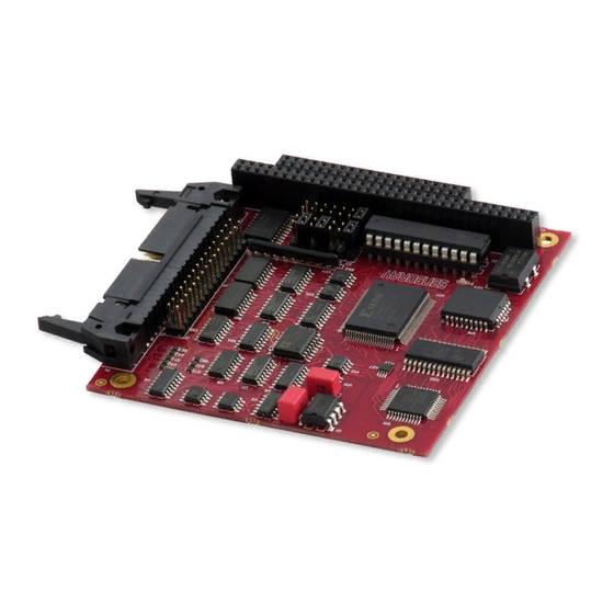
1.1 Functional overview Model 518 is a PC/104 circuit board that interfaces any combination of up to eight sensors to a host computer. Each sensor channel provides complete signal conditioning for a variety of sensor types, thus allowing any channel to be directly connected to a thermocouple, RTD, strain gauge, thermistor, resistor, 4-to-20 mA current loop, or DC voltage. -
Page 6: Chapter 2: Configuration And Installation
To avoid address conflicts, you must map the board into an address range that is not used by other devices. Model 518 does not decode the full PC/104 16-bit I/O address; only the low ten address bits are decoded. Consequently, aliased “images” of the 518 will appear throughout the 16-bit address range at intervals of 0x400 bytes. -
Page 7: Thermocouple Shunts
Connect an external field-wiring termination board to connector P1 with a 40-conductor flat ribbon cable. • Sensoray recommends the model 7409TB termination board and 7409C cable for this purpose. Connect your sensors to the termination board as required. See Sensor connections for details. -
Page 8: Chapter 3: Sensor Connections
3.1 Connector P1 All sensors connect to the board via connector P1. Optionally, sensors may be connected to a Sensoray model 7409TB screw termination board, which in turn connects to P1 via ribbon cable. A 7409TB (or equivalent) is required if you are measuring thermocouples as it provides an essential temperature transducer for cold junction compensation. -
Page 9: Thermocouples And Voltage
Thermocouple wires are color coded to indicate polarity. The positive thermocouple wire should be connected to the V+ terminal and the negative thermocouple wire should be connected to the V- terminal (the red thermocouple wire is negative by convention). 518 Instruction Manual Sensor connections... -
Page 10: Strain And Pressure Gauges
The board supports 4-20 mA current loop inputs on any channel when an optional 250-ohm 0.01% resistor is installed as shown below. These resistors are available as an option for model 518: order Sensoray part number 7408R. Note: The sensor channel must be located at the ground end of the current loop so that common mode voltage will not exceed 5 V. -
Page 11: Chapter 4: Register-Level Programming
The base address consists of two hardware registers: command and data. When the host sends a command byte to the 518, it is storing a byte in the board's command register. When the host reads a reply byte from the 518, it is fetching a byte from the board's data register. -
Page 12: Control Register
4.4 Handshaking If you will not be using Sensoray's 518 API (e.g., you are developing for DOS, etc.), it is recommended that you create functions that mask the handshake protocol from higher software layers. The following C language examples show how to do this. -
Page 13: Endianness
// send low byte // Fetch a 16-bit value from the board int ReadWord(int base_port) int hiByte = ReadByte(base_port) << 8; // fetch high byte return (hiByte | ReadByte(base_port)); // fetch & concatenate low byte 518 Instruction Manual Register-level programming... -
Page 14: Chapter 5: Commands
5.1 Overview The 518 board is controlled and monitored by sending it commands. Each command consists of at least one byte, but commands vary in length depending on the size of associated data. In some cases, the board will respond to a command by sending data back to the host. -
Page 15: Readchannel
The second command byte contains bit flags (one per channel) that specify whether each channel will indicate the minimum or maximum possible value upon open-sensor detection: 518 Instruction Manual Commands... -
Page 16: Setlimits
Example: // A closed-loop heat controller monitors temperature via a thermocouple // on channel 1. If the thermocouple opens, the 518 should indicate a high // temperature to ensure that the heater turns off. This code sets up // channel 1 to fail high (all other channels will fail low). -
Page 17: Gauge Commands
// is monitored by load cell connected to channel 7. Channel 7 has been // previously calibrated using the SET gauge ZERO and SET gauge SPAN commands. SendByte(port, 112 + 7); // issue command: (opcode + channel) 518 Instruction Manual Commands... -
Page 18: Readgaugecalibration
SendByte(port, 144 + chan); for (i = 0; i < 6; i++) SendByte(port, array[i]); 5.5 Miscellaneous commands 5.5.1 ReadFirmwareVersion This command returns the firmware version number (times 100). Command: (240), (5), (0) Response: (VERS_MSB), (VERS_LSB) Example: 518 Instruction Manual Commands... -
Page 19: Readboardtemperature
This command returns the temperature of an optional, external reference sensor (e.g., on a 7409TB termination board), which is required when thermocouples are being measured. This function can also be used as a debug aid during 518 installation. The returned integer value is scaled to 0.10 °C/bit. If no reference temperature sensor is connected, this command will return a meaningless value. - Page 20 SendByte(port, 224 + chan); // issue Calibrate command: SendByte(port, chan); CALCODE SendWord(port, (int)(ref[chan] * scalar[chan])); cal data ReadByte(port); // wait for calibrate to complete outp(port + 1, 0); // reset 518 board Sleep(500); // wait for board to reboot 518 Instruction Manual Commands...
-
Page 21: Chapter 6: Sensor Specifics
Model 518 requires the gauge to be part of a full bridge circuit, with a bridge input resistance of at least 120 Ω. Furthermore, the bridge output voltage must fall within the range -500 mV to +500 mV under all load conditions (including offset due to bridge imbalance). -
Page 22: Setting Zero And Span
The board will automatically subtract the tare weight of a load container from the measured gross weight. To enable this, do the following: 1. Position the empty container/vehicle on the load cell. 2. Issue a TareGauge command to the board. Subsequent channel data will indicate the corrected payload weight. 518 Instruction Manual Sensor specifics... -
Page 23: Chapter 7: Timing
R = number of response bytes Examples: Number of bytes Command Total time Command Response ReadChannel 30 + 20 * (1 + 2) = 90 µs ReadAllChannels 30 + 20 * (1 + 16) = 350 µs 518 Instruction Manual Timing... -
Page 24: Chapter 8: Specifications
+5 VDC ±5% @ 100 mA (nominal) +12 VDC ±5% @ 45 mA -12 VDC ±5% @ 35 mA Rev V+ boards +5 VDC ±5% @ 300 mA Temperature Operating 0 to +70 °C Storage -25 to +85 °C 518 Instruction Manual Specifications... -
Page 25: Sensor Specifications
0.01 % (4 mA=0%, 20 mA=100%) Resistance 0x0A 0 to 400 Ω 0.04 Ω 0.02 Ω 0x14 0 to 4 KΩ 0.25 Ω 0.125 Ω 0x20 0 to 600 KΩ 130 Ω 31 Ω Disabled channel 0x13 518 Instruction Manual Specifications... -
Page 26: Chapter 9: Limited Warranty
The reader should consult Sensoray if errors are suspected. In no event shall Sensoray be liable for any damages arising out of or related to this document or the information contained in it.
Need help?
Do you have a question about the 518 and is the answer not in the manual?
Questions and answers