Table of Contents
Advertisement
Quick Links
Advertisement
Table of Contents

Related Manuals for SOLZAIMA SZM A PLUS 16 kW


Summary of Contents for SOLZAIMA SZM A PLUS 16 kW
- Page 1 Pellet Boilers Instruction Manual English Models SZM A PLUS 16 kW SZM A PLUS 24 kW SZM A PLUS 32 kW Read these instructions carefully before installing, using and servicing the unit. The product is supplied with this instruction manual.
- Page 2 * SOLZAIMA is not responsible for any damage to units installed by non-qualified personnel; * SOLZAIMA is not responsible for any damage to units not installed and used in compliance to the instructions included in this manual; * All local regulations, including but not limited to national and European standards, must be observed when installing, operating and servicing the unit;...
-
Page 3: Table Of Contents
Contents Solzaima ....................1 Package content..................2 Safety precautions ................4 3.1. Advice in the event of a chimney fire ............6 Technical specifications ................7 4.1. General vies ..................8 4.2. Connections views .................. 9 Installation of the pellet-run boiler ............10 5.1. - Page 4 12.2. Removing the bottom ash drawer ............46 12.3. Forcing the burner plate clean ............... 47 12.4. Annual cleaning ................... 49 12.5. Cleaning the glass ................54 Alarms / failures / recommendation list ..........55 Maintenance plan and log ................ 57 Maintenance guide label ................
-
Page 5: Solzaima
1. Solzaima Solzaima's vision has always been to provide the cleanest, renewable and more cost- effective energy. This is why we have been dedicated to manufacturing biomass heating equipment and solutions for the past 45 years. Due to its persistence and the unconditional support of its network of partners,... -
Page 6: Package Content
2. Package content Solzaima ships the unit with the following components: - Boiler model SZM A PLUS; - Leaflet for accessing the online instruction manual; - Power cable. The boiler is a bulky and heavy object, make sure it is as close as possible to the installation site before unpacking. - Page 7 The boiler is attached to the pallet with screwed parts that secure the feet at each corner of the boiler. Remove the bolts to remove the boiler from the pallet. Carefully lower the body of the pallet, making sure to do so on a protected floor area. Although the boiler has rubber levelling feet, there are protruding metal parts which can easily damage the floor.
-
Page 8: Safety Precautions
3. Safety precautions Solzaima will not assume any responsibility if the precautions, warnings and operating standards of the equipment are not respected. The equipment manufactured by Solzaima is simple to operate and special attention has been given to its components in order to protect the user and the installer against possible accidents. - Page 9 Do not tamper with safety or adjustment features without the manufacturer's authorization; Do not cover or reduce the size of the vents at the installation area; The pellet-run boiler requires good air supply to guarantee correct combustion; as ...
-
Page 10: Advice In The Event Of A Chimney Fire
The surface on which the boiler is installed must be made of non-flammable material and be well levelled; The machine is not a condensing boiler, it must work in the conditions for which it was designed; It is recommended to regularly check that the boiler is in good condition. ... -
Page 11: Technical Specifications
4. Technical specifications SZM A SZM A SZM A Features Units PLUS PLUS 24kW PLUS 32kW 16kW Weight Height 1360 1360 1530 Width 1123 1123 1123 Depth Diameter of the fume discharge pipe Reservoir capacity Dimensions of the pellet tank inlet 235x350 235x350 235x430... -
Page 12: General Vies
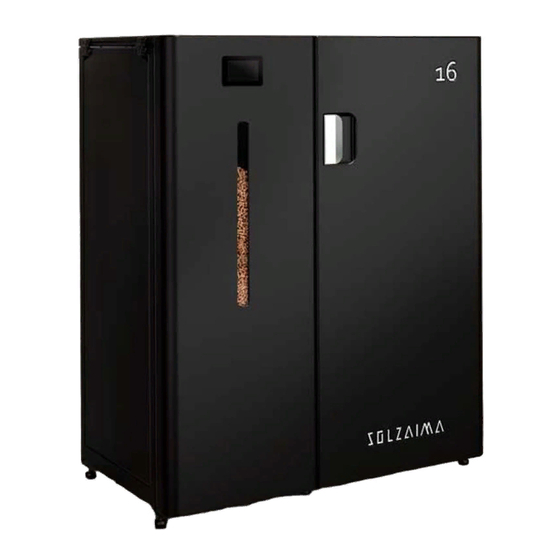
4.1. General vies SZM A PLUS 16 kW Front Side Rear Figure 3 A - Dimensions of the SZM A PLUS 16 kW boiler SZM A PLUS 24 kW Front Side Rear Figure 3 B - Dimensions of the SZM A PLUS 24 kW boiler... -
Page 13: Connections Views
4.2. Connections views Figure 4 – Pellet boilers connections SZM A PLUS 16, 24 and 32 kW... -
Page 14: Installation Of The Pellet-Run Boiler
5. Installation of the pellet-run boiler 5.1. Before installation Before starting the installation, carry out the following actions: Check immediately on receipt that the delivered product is complete and in good condition. Any defects should be reported before installing the appliance. ... -
Page 15: Minimum Distances
5.2. Minimum distances The following figure shows the minimum distances between the pellet boiler and particularly inflammable surfaces. On top of the boiler, it is necessary to maintain a minimum distance of 1 m from the ceiling of the room especially if these contain inflammable material in their composition. -
Page 16: Installation Of Room Thermostat Or Chrono-Thermostat
Figure 7 - Minimum surface distances Warning! Keep combustible and flammable materials at a safe distance. 5.3. Installation of room thermostat or chrono-thermostat The boilers come prepared with a connector for connecting an ambient thermostat or a chronothermostat on the back. The contact is voltage-free and will instruct the boiler to switch on (contact closed) or off (contact open). -
Page 17: Installation Kit Silo Enlargement 225L (Optional)
5.4. Installation kit silo enlargement 225L (optional) For the 16 kW and 24 kW boilers a silo extension kit can be purchased which increases the silo capacity according to Table 2. Silo capacity* Original With Kit Capacity in kg Capacity in litres Table 2 - Silo capacity with extension * Type of fuel = Pellet (EN 14961-2 A1) diameter 6 mm/ L 10-30 mm. - Page 18 Figure 9 - Removal of the screws that fix the side of the boiler Then open the boiler door to gain access to the screws that secure the front of the unit and remove it, you must also loosen the screws on the display. Figure 10 - Removal of the screws that fix the side of the boiler...
- Page 19 After removing the side and front of the equipment, remove all the screws that fix the side, Din 7981 screws 4,2x9,5, and the front of the silo, Din 912 screws 8.8 M4x12. Figure 11 - Removal of the screws from the side and front of the silo You must then apply the silo lateral that is contemplated in the extension kit using the screws that are sent along with the kit.
- Page 20 Put the front of the silo back on and then you should apply the side and front that come with the kit. Figure 13 - Silo front application Figure 14 - Application of the side and front of the equipment...
- Page 21 With the application of this kit the width of the boilers, both the 16 kW and 24 kW change, increases by 125 mm. The height and depth remain the same. Figure 15 - Boiler dimensions with and without silo extension kit...
-
Page 22: Installation Of Pipes And Fume Exhaust Systems
6. Installation of pipes and fume exhaust systems • The exhaust pipe must have been designed for this purpose, in compliance to the location requirements and in accordance with any applicable regulations. Under rated operating conditions, the flue gas draught must give rise to a ... - Page 23 Figure 16 - Side view of the installation without chimney...
- Page 24 In the following picture, the requirements for the installation of the flue duct are shown. Figure 17 - Example of flue duct installation A...
- Page 25 Figure 18 - Example of flue duct installation B...
- Page 26 Figure 19 - Example of flue duct installation C Failure to comply with the requirements here detailed may prevent the correct operation of the unit. Follow all the instructions presented on the diagrams. The boilers operate with the combustion chamber in depression, which is why it is absolutely necessary that they include a fume exhaust pipe to adequately extract combustion gases.
- Page 27 Fume duct material: The tubing must consist of 0,5 mm thick rigid stainless steel, with fastening joints attaching the different sections and accessories. Insulation: The fume ducts must be double-walled and insulated to make sure that fumes do not cool down going outwards, which would cause an inadequate circulation and condensation that may damage the unit.
-
Page 28: Installation With Chimney
6.2. Installation with chimney The installation of the pellet boiler brings the flue pipe directly into the chimney. If the size of the chimney is too large, it is recommended to pipe the smoke outlet with a tube with an internal diameter which must be at least equal to that of the boiler's smoke outlet. -
Page 29: Hydraulic Installation
6.3. Hydraulic installation Chapter 16 shows the possible installation schemes in the context of a central heating installation, with or without domestic water heating system; The return temperature regulation valve causes the water to recirculate only through the inside of the boiler until it reaches a temperature of 55ºC, when this temperature is reached the valve opens allowing the hot water from the body to circulate through the installation, but always maintaining a mixture with hot water from the body which guarantees a return temperature that does not create... - Page 30 The pellet boiler incorporates a circulation pump, a 16-litre expansion vessel, a 3- bar safety valve, a filling tap and a return temperature control valve (anti- condensation valve); The expansion vessel is 16 litres and is pre-charged to 1 bar, this volume and ...
- Page 31 Inlets for hydraulic connections. Bomba Instalação Instalation Pump Válvula 3 vias A.Q.S. 3 way valve D.H.W. Termostato Ambiente Room Thermostat Sonda NTC 10K A.Q.S D.H.W NTC 10K Probe Sonda NTC 10K Dep. Inércia Buffer Tank NTC 10K Probe Figure 22 - Hydraulic connections It is very important to fill the boiler using the correct connection, as the boiler has ...
-
Page 32: Electrical Installation
6.4. Electrical installation The electrical mains must be single-phase at 230v 50Hz, and a two-pole circuit breaker must be installed between the mains and the boiler. The boiler must always be earthed. The elements external to the boiler as well as the power supply are carried out ... - Page 33 If you purchase the Wi-Fi module, it should be connected to the interface already installed in the machine, and you do not need to apply the Wi-Fi kit interface. Figure 24 - Interface kit Wi-Fi In section 16 you can find the wiring diagram of the electrical board. ...
-
Page 34: Fuel
7. Fuel The boiler must be exclusively fuelled by pellets. No other fuel may be used. Use only pellets certified by standard EN 14961-2 grade A1, 6mm in diameter and a length between 10-30mm. The pellets may have a maximum humidity of 8% their weight. To guarantee a good combustion, the pellets must maintain these characteristics so they should be stored in a dry place. -
Page 35: Use Of The Pellet-Run Boiler
8. Use of the pellet-run boiler Before starting up the unit, please check the following: Guarantee that the boiler is properly connected to the power mains by means of the 230 VAC power cable. Figure 26 - Electric power plug Check that the pellet reservoir is full. -
Page 36: Display
The boiler's combustion chamber is made of iron sheeting painted with high- temperature paint, which releases fumes during the first burns due to the curing of the paint. 9. Display The boiler is controlled using the touchscreen located on the top front of the boiler. This 4.3"... - Page 37 By pressing the button located in the upper right part of the screen, a new screen will open, in which you can see a list with the codes of the errors that have occurred, ordered by dates. To return to the main menu click on the house design you will find at the top left. From the main screen, by pressing on it and sliding your finger to the left, you will access a general screen that will show the status of the 8 main electrical components of the boiler.
-
Page 38: Viewing And Eliminating Errors
This top bar is divided into 4 parts: - The first shows the selection of the operating mode: summer or winter. If you select "summer" mode, the system will only work for DHW but not for central heating, although the thermostat requires it, if you select "winter" mode, the system will give priority to DHW and will run central heating when the chrono and room thermostat requires it. -
Page 39: Settings Menu
If an error appears, the first thing to do is to correct the cause for which the error occurred (chapter 13), if you are unable to do so, contact the technical assistance representative. With the cause of the error eliminated, press the button to switch the boiler on again and close the error message. - Page 40 The first button "COMBUSTION” , shows the options that can be set that affect combustion: selected power, calibration of the pellet worm motor and calibration of the smoke extractor speed. Note: These functions allow the quantity of pellets and the rpm of the extractor to be increased or reduced by up to 25% during the start-up and power-up process.
-
Page 41: Display Menu
The second button "SYSTEM MENU" , allows entering the advanced configuration menu, and is reserved for the exclusive use of Solzaima authorized technicians. For this reason, this menu is password protected and is not available to the final consumer. -
Page 42: Info Menu
9.5. Info menu By pressing the fourth button on the lower bar of the main screen, "INFO MENU" , the following window appears. In this window, it is possible to view all the information in real time, not only for the boiler, but for the entire installation. The information displayed on this screen will depend on the elements installed (inertia tank and DHW tank). - Page 43 On the first chrono configuration screen you can choose between editing a daily, weekly or weekend programme (you can only have one option active; they do not work simultaneously). To do this, click on the icon below the option you want to edit.
-
Page 44: Processes
Notes: - After configuring the programmes, do not forget to enable them. - We can only have one programme active in the Chrono: daily, weekly or weekend (they do not work simultaneously). - When the chrono is enabled, it is possible to verify that it is active on the display on the main screen. -
Page 45: Stop
The display must indicate "Ignition" and remain so until the ignition phase is complete. The pellets are led through the feed channel to the firing basket (combustion chamber) where they are ignited by the heating element. This process may take between 10 and 15 minutes, depending on whether the pellet auger has been previously loaded or emptied with fuel. -
Page 46: Filling The Pellet Reservoir
11. Filling the pellet reservoir 1 - Open the top left-hand cover by pulling the handle upwards. Follow the movement to avoid abrupt lid movements. The cover remains open at 90º, leaving the top of the pellet silo visible. This has a grid on the top which will help us when loading, firstly because it allows us to support the bag and secondly because it acts as a filter, preventing unwanted things from falling into the silo. -
Page 47: Maintenance
12. Maintenance Solzaima pellet boilers require rigorous maintenance like any other machine of this type. The main precaution to be taken is to regularly clean the ash from the collection drawers. Cleaning should be carried out after firing approximately 1200 kg, which may vary greatly depending on the quality of the pellets used. - Page 48 - Once the inner door has been opened and with the help of the lid hanging on the inside outer door, remove the ash drawer from the burner. Figure 30 - Removing the ash drawer from the burner - To do so, move the drawer outwards little so that it is easier...
- Page 49 - Pull a little upwards and then outwards to move the drawer out of its place. See sectional image. Figure 32 - Removing the ash drawer from the burner - Insert the flap from the back towards the end first. This way, the flap will protect you from the possible heat that the ashes may...
-
Page 50: Removing The Bottom Ash Drawer
Give a small downward twist so that the top flap enters through the slot and move the lid towards you. You will soon notice that the lid is fitted onto the drawer. This allows you to take the drawer wherever want empty it. -
Page 51: Forcing The Burner Plate Clean
- Fit the lid onto the drawer by making the tabs on the drawer engage the hooks on the lid. This way you can take the ash drawer wherever you want to empty it. Figure 36 - Removing the ash pan from the turbulators 12.3. - Page 52 Figure 37 - Cleaning the burner plate When everything is clean and the drawers are in place, simply close the inner door. The boiler has a limit switch that detects that the door is closed and automatically brings the burner plate to its working position. Figure 38 - Cleaning the burner plate...
-
Page 53: Annual Cleaning
This complete cleaning must be carried out by a technician authorised by Solzaima. To start with the boiler must be completely cold, as the internal parts of the boiler will be dismantled and cleaned and must be cold to avoid unnecessary scratches. - Page 54 Removing the outer cover leaves the smokebox cover uncovered. This cover is fixed to the boiler body with 4 Din 912 M10 screws, to remove them it is necessary to use a nº8 screwdriver. It is advisable to loosen all the screws a little before loosening them completely to make the operation easier and so that none of the screws are forced too far.
- Page 55 When the flue box lid is removed, the entire inside of the flue box is visible. The fume extractor inlet, the 6 heat exchanger tubes, the automatic tube cleaning system and the fume box lid can be seen. To remove the cleaning system, loosen the DIN 912 M6x20 screws that secure the inner shaft to the outer shaft and move it towards the outer shaft.
- Page 56 To be able to remove the inner cover, you must first remove the 4 fixing systems (detail A). Loosen the DIN M10x30mm screws, move the fixing system backwards and remove it by turning it upwards. Do not remove the screw completely so that it is easier to put it back in later.
- Page 57 After this step, you have access to the entire interior of the body. As usual, clean with a wire brush scraping the walls from top to bottom, removing ash and any debris that may be in the combustion chamber or pipes. Be careful not to damage the ceramic paper on the safety valve and the fume probe next to it (marked with arrows in the following figure).
-
Page 58: Cleaning The Glass
Place the outer cover on the body and secure the screws securing it by hand before tightening them alternately so that the force is distributed properly. Fit the cover by matching the spring clips to the protruding pins and force the cover downwards. -
Page 59: Alarms / Failures / Recommendation List
13. Alarms / failures / recommendation list Error Description Actions - Check electrical connection. - Check that the pump works. Er01 Alarm thermostat safety - Bleed the hydraulic circuit. - If the problem persists, contact technical service. - Close door and remove faulty pressure switch error. Er02 Alarm smoke pressure switch - Blockage of exhaust pipe or defective extractor. - Page 60 - Check electrical connection. Boiler probe or inertia tank probe Er23 - Restart the boiler, if the problem persists, contact open technical service. Er25 Burner cleaning motor broken - Motor Clean burner broken or blocked. Er26 Broken cleaning motor - Motor Clean burner broken or blocked. Differential pressure sensor...
-
Page 61: Maintenance Plan And Log
ANOMALY DOES NOT INFLUENCE THE NORMAL OPERATION OF THE BOILER, IT IS MERELY A WARNING. Important notice: any error can only be cleared if the boiler is in "Lock". Important notice: the anomalies do not cause the unit to shut down. WARNING In case of an emergency, switch the unit off using the standard shutdown procedure. -
Page 65: Maintenance Guide Label
15. Maintenance guide label Figure 47 - Maintenance label Note: The safety warnings sticker label is attached from factory to the unit’s pellet lid, in the Portuguese language. Attached to the manual you will find other language versions of the sticker labels (Spanish, English, French and Italian). If necessary, remove the Portuguese language label and replace it with the label in your country’s language. -
Page 66: Installation Diagrams
16. Installation diagrams 16.1. Simple connection only the central heating radiators Figure 48 - Simple connection only the central heating radiators Notes: TA the boiler can be used, with the application of a generic external control (chronothermostat) or another type of control provided that it is voltage-free (dry contact). -
Page 67: Connection To Central Heating Radiators And Sanitary Water Combined With Solar Panel
16.2. Connection to central heating radiators and sanitary water combined with solar panel Figure 49 - Connection to central heating radiators and sanitary water combined with solar panel Notes: TA the boiler can be used, with the application of a generic external control (chronothermostat) or another type of control provided that it is voltage-free (dry contact). -
Page 68: Connection To Central Heating Radiators, With Inertia Tank And Installation Pump
16.3. Connection to central heating radiators, with inertia tank and installation pump Figure 50 - Connection to central heating radiators in combination with another boiler, storage heaters, domestic hot water and in combination with a solar panel Approximate calculation of the inertia tank: Pellet boilers are recommended to have an inertia tank of 20l per kW. -
Page 69: Combined Heating Connection, Hot Water With Inertia Tank And Domestic Hot Water
16.4. Combined heating connection, hot water with inertia tank and domestic hot water Figure 51 - Connection for underfloor heating, together with another boiler, domestic hot water and combination with solar panel Approximate calculation of the inertia tank: Pellet boilers are recommended to have an inertia tank of 20l per kW. -
Page 70: Electrical Connection Diagram
17. Electrical connection diagram Yellow Yellow Black Brown Yellow Yellow Grey Grey Green Ventilator Green Exchanger cleaning White Blue Boiler Pump Encoder Black Brown Ventilator Blue Resistance Blue White Pressure Green Purple TS Boiler Sensor Brown Purple TS Silo White Pressure switch Green White... -
Page 71: Circulator Pump Operation
18. Circulator pump operation UPM3 pump with Hybrid 25-70 130mm Circulating pump performance graph Figure 53 - Pump performance graph User interface The user interface is designed with a single button, one red/green LED and four yellow LEDs. BUTTON Figure 54 - User interface... - Page 72 When the pump is running, LED 1 is green. The 4 yellow LEDs indicate the current performance of the pump as shown in the table below. LED active Performance (%) LED green 0 (Standby) 0-25 LED green + 1 LED yellow 25 - 50 LED green + 2 LED yellow 50-75...
- Page 73 Figure 56 - Pump settings Maximum manometric height (m) Configuration Table 6 - Pump settings Alarms If the pump detects one or more errors, the LED 1 changes from green to red when the alarm is activated the yellow LED indicates the type of alarm (see Table 6), if we have several alarms at the same time, the yellow LED indicates the alarm with higher priority, the priority sequence is defined on table as follows: Display...
-
Page 74: Annexes
19. Annexes 19.1. Function flow diagrams Flow chart 1 – Normal activation Note: The first time you will have to activate it manually by pressing the on/off button , and also after an error has occurred. - Page 75 Flow chart 2 – Disconnecting the machine Note (only for the water version): The circulator is switched off below 40 °C water temperature.
-
Page 76: Life Cycle Of A Pellet Boiler
Solzaima makes all efforts to learn and to know the national forest park while efficiently responding to energy demands, taking permanent care to maintain its biodiversity and natural wealth that are essential for the quality of life on our planet. -
Page 77: Glossary
22. Glossary Ampere (A): SI unit of measurement of electric current bar: unit of pressure equal to exactly 100,000 Pa. This pressure is very close to standard atmospheric pressure. cal (Calorie): equal to the amount of heat required to increase the temperature of one gram of water by one degree centigrade. - Page 78 value is expressed in calories (or kilocalories) per unit of weight of fuel. Oxidiser: chemical substance that feeds combustion (essentially oxygen) and is essential for it to take place. Pa (Pascal): standard IS unit of pressure and tension. This unit is named after Blaise Pascal, eminent French mathematician, physicist and philosopher.
-
Page 79: Warranty
3.1.2 A term of 6 months from the date of delivery of the goods, in the case of professional, or industrial, or intensive use of the products - Solzaima means... - Page 80 In order to exercise its rights, and provided that the term indicated in 3.1 is not exceeded, the Buyer must report in writing to Solzaima, S.A., the lack of conformity of the Product within a maximum period of: 3.5.1 60 (sixty) days after the date on which it has detected it in the case of domestic use of the product;...
- Page 81 acquisition. In any case, the document proving the acquisition of the Product must contain the identification of the Product (as mentioned in point 2 above) and its date of acquisition. Alternatively, and in order to validate the Product Warranty, the PSR - document certifying the commissioning of the machine (when applicable)).
- Page 82 Whenever requested, it must be proved by submitting the technical report of the entity responsible for it, or alternatively by registering them in the instruction manual in the dedicated section. 3.12 In order to avoid damage to the equipment caused by overpressure, safety elements such as pressure relief valves and / or thermal discharge valves, if applicable, as well as an expansion vessel fitted to the installation, shall be ensured at the time of installation and its correct functioning must be ensured.
- Page 83 Buyer, and the Buyer shall be responsible for any charges arising therefrom. 3.17 The Warranty is valid for the Products and equipment sold by Solzaima SA solely and exclusively within the geographical and territorial zone of the country where the Product was sold by Solzaima.
- Page 84 4.8. Defects caused by the use of accessories or replacement components other than those determined by Solzaima, S.A.; 4.9. Defects arising from non-compliance with the installation, use and operation instructions or applications not conforming to the intended use of the Product, or from abnormal climatic factors, unusual operating conditions, overload or maintenance or cleaning performed improperly;...
- Page 85 4.16. The installation of the equipment supplied by Solzaima, S.A. should contemplate the possibility of their easy removal, as well as points of access to the mechanical, hydraulic and electronic components of the equipment and the installation.
- Page 86 Solzaima have a 6-month guarantee. Warranty Spare Parts provided by Solzaima The parts supplied by Solzaima, as part of the commercial sale of spare parts, i.e., not incorporated in the equipment, have no guarantee. Replaced Parts under the of Scope Technical Service From the moment they are removed from the equipment, the Parts used are considered as waste.
- Page 87 from giving them another destination, whatever. Therefore, the customer will be able to see the used parts resulting from the assistance, but cannot keep them in their possession. Administrative expenses In the case of invoices for services rendered, they are not processed in any stipulated period with default interest at the maximum legal rate in force.
Need help?
Do you have a question about the SZM A PLUS 16 kW and is the answer not in the manual?
Questions and answers