Table of Contents
Advertisement
Quick Links
PROJECT NAME
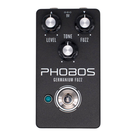
PHOBOS
BASED ON
Tone Bender Mk. III (3-knob)
EFFECT TYPE
Germanium fuzz
PROJECT SUMMARY
A reproduction of the third version of the Tone Bender germanium fuzz sold by Macaris in London in the
late 1960s.
This documentation is for the kit version of the project. If you purchased the PCB by itself, please
use the
PCB-only version
are completely different due to the specialized parts and assembly methods used in the kit.
PHOBOS GERMANIUM FUZZ
LEVEL
HO OS
GERMANIUM FUZZ
IMPORTANT NOTE
of the documentation instead. The circuit is the same, but the instructions
BUILD DIFFICULTY
Intermediate
DOCUMENT VERSION
1.0.1 (2022-07-01)
9V
TONE
FUZZ
1
Advertisement
Table of Contents

Related Manuals for aion PHOBOS


Summary of Contents for aion PHOBOS
- Page 1 This documentation is for the kit version of the project. If you purchased the PCB by itself, please use the PCB-only version of the documentation instead. The circuit is the same, but the instructions are completely different due to the specialized parts and assembly methods used in the kit. PHOBOS GERMANIUM FUZZ...
-
Page 2: Table Of Contents
23 Enclosure Layout: Main & Footswitch PCBs 24 Enclosure Layout: Input/Output PCB 25 Final Assembly & Biasing 26 Final Assembly (Cont.) 27 Schematic 28 Full Parts List 29 Troubleshooting Information 30 Support & Resale Terms 31 Legal Information & Document Revisions PHOBOS GERMANIUM FUZZ... -
Page 3: Introduction
INTRODUCTION If this is your first pedal, welcome to the hobby and thank you for choosing Aion FX. You’ve just joined a community of over 40,000 people around the world with a passion for building homemade noise machines using obsolete electronics technologies, and we’re glad to have you! If you’ve done this before, it’s great to see you again and we’re confident you’ll find this build experience... - Page 4 MLCC Capacitors NAME TC1044SCPA or LT1054CP NAME 8-pin socket 220pF (marked “221”) 100n (marked “104”) Transistors 470n (marked “474”) NAME Diodes Transistors, germanium, matched for Tone Bender Mk. III NAME Trimmers 1N5817 1N4742A NAME 1N34A (germanium) 10k trimmer PHOBOS GERMANIUM FUZZ...
- Page 5 LED bezel 4-pin wire assembly header LED, blue 9V battery snap DC jack Input/output jack Mounting nut, jack, 0.54" Outer washer, jack, 0.6" Lock washer, jack, 0.5" (thin) Enclosure Enclosure screws PCB, main circuit PCB, footswitch PCB, input/output/DC PHOBOS GERMANIUM FUZZ...
-
Page 6: Tools Needed
The tip should used to tighten the dress nut to avoid lot of pedals! be no more than 0.1” (2.5mm) wide. scratching or denting it (which can happen with metal tools). PHOBOS GERMANIUM FUZZ... -
Page 7: Component Identification
“multi-layer ceramic capacitor.” is marked. OP-AMP / IC IC SOCKET TRANSISTOR OR JFET TRANSFORMER Charge pumps and delay chips also look like this. They may have more than 8 legs. WIRE ASSEMBLY WIRE ASSEMBLY HEADER DC JACK LED BEZEL PHOBOS GERMANIUM FUZZ... -
Page 8: Hardware Identification
MOUNTING NUT DRESS NUT LOCK WASHER DIAMETER: 0.36” / 9.1mm DIAMETER: 0.375” / 9.5mm DIAMETER: 0.4” / 10.1mm FOOTSWITCH MOUNTING NUT DRESS NUT LOCK WASHER DIAMETER: 0.6” / 15.2mm DIAMETER: 0.77” / 19.6mm DIAMETER: 0.6” / 15.2mm PHOBOS GERMANIUM FUZZ... -
Page 9: Pcb Assembly Overview
Generally speaking, you should populate the components in this order: 1. Resistors 2. Diodes 3. IC sockets 4. Trimmers 5. MLCC capacitors 6. Film capacitors 7. Electrolytic capacitors 8. Germanium transistors PHOBOS GERMANIUM FUZZ... -
Page 10: Resistors
You don’t want to practice or experiment on this board! Note: R6 may be either a red 18k resistor or a brown 18.2k resistor depending on availability. In this position, the 1% difference in value won’t have any impact on the circuit. PHOBOS GERMANIUM FUZZ... -
Page 11: Diodes
• Be quick when soldering. Germanium diodes can easily be damaged by overheating. Limit contact with the soldering iron to 1-2 seconds maximum. If you don’t have a good solder joint, wait a minute or two for it to cool before trying again. PHOBOS GERMANIUM FUZZ... -
Page 12: Socket & Ic
ICs may have two different orientation marks: either a dot in the upper-left or a half-circle notch in the middle of the top side. Some ICs have both marks. This shows which way the IC should be rotated when inserting it into a socket (the socket also has a half-circle notch). PHOBOS GERMANIUM FUZZ... -
Page 13: Trimmers
The trimmers can be soldered like normal components, by bending the legs outward as shown: These trimmers are used to bias the germanium transistors. We will adjust them at the end once the pedal is fully assembled. PHOBOS GERMANIUM FUZZ... -
Page 14: Capacitors (Non-Polarized)
Note: C6 (box film capacitor) may be either blue or red. The blue one will have the value printed on the top, while the red type would have the value on the side. The text on the side of the blue capacitors is not related to the value and can be ignored. PHOBOS GERMANIUM FUZZ... -
Page 15: Wire Headers
They do fit pretty tightly in the holes, though, so press firmly. There’s also a 4-pin header on the I/O board that we will do in a later step. PHOBOS GERMANIUM FUZZ... -
Page 16: Capacitors (Polarized)
The longer leg is positive and fits in the square pad. At this point, we only have the transistors left to do, so now is a good time to go back and insert the IC into the socket (page 12). PHOBOS GERMANIUM FUZZ... -
Page 17: Germanium Transistors: Introduction
Q1-Q3, not by specific part numbers such as AC125 or MП16Б. Matching The transistors included in the Phobos kit have been measured and matched for best performance in the Tone Bender circuit. There are three bags labeled Q1, Q2 and Q3. -
Page 18: Germanium Transistors: Q1 And Q2
The base pins are connected to the metal casing, so anything they touch will be shorted against the base. If they’re touching, just bend them slightly away from each other and they should remain that way. PHOBOS GERMANIUM FUZZ... -
Page 19: Germanium Transistors: Q3
Q3 will partially overlap the biasing trimmers on the right-hand side of the board, so make sure there is enough clearance that the trimmers can be easily adjusted later. PHOBOS GERMANIUM FUZZ... -
Page 20: Footswitch Pcb
BLUE MARKING Once all three wire assemblies are soldered, set the footswitch PCB aside. We’ll solder the actual footswitch and LED in a later step. PHOBOS GERMANIUM FUZZ... -
Page 21: Input/Output Pcb
Red is positive (+), black is negative (-). After soldering, pull it tight. For even more strain relief, you can thread the snap through the loop to form a knot. (not shown) PHOBOS GERMANIUM FUZZ... -
Page 22: Enclosure Layout: Panel Mounts
You’ll need to hold the bezel in place when OUTER WASHER tightening the nut. The top of the bezel is fairly MOUNTING NUT sharp, so try using a rubber band for grip instead of pressing your finger against the bottom. PHOBOS GERMANIUM FUZZ... -
Page 23: Enclosure Layout: Main & Footswitch Pcbs
However, Aion FX projects are designed to be extremely easy to remove from the enclosure for troubleshooting, with no desoldering required—so with these kits, it’s actually much easier to “box it before you rock it”. -
Page 24: Enclosure Layout: Input/Output Pcb
Note the use of two mounting nuts on each of the jacks, one inside and one outside. The inner nut acts as a spacer to set the DC jack flush with the outside of the enclosure. The inner nuts should be threaded as far down as they can go. MOUNTING NUT OUTER WASHER LOCK WASHER MOUNTING NUT 125B PHOBOS GERMANIUM FUZZ... -
Page 25: Final Assembly & Biasing
Plug in a 9-volt supply and test it out with a guitar and an amplifier. Test the bypass switch a few times, then start turning the controls and see if everything sounds OK. If it works, great! If not, don’t be discouraged. See page 29 for troubleshooting info. PHOBOS GERMANIUM FUZZ... -
Page 26: Final Assembly (Cont.)
Last, just close the panel on the back using the four screws. Before that, though, grab a permanent marker and write your name and the completion date on the inside of the back panel. This is an accomplishment! PHOBOS GERMANIUM FUZZ... -
Page 27: Schematic
SCHEMATIC 1N5817 100uF 100n 10uF TC1044SCPA PWR_GND PWR_GND 470n 47uF PWR_GND PWR_GND Q3 BIAS 10kB 220k FUZZ 100kB 220pF 10uF GND GND PHOBOS GERMANIUM FUZZ... -
Page 28: Full Parts List
100n (0.1) 100n MLCC 2n2 (0.0022) Potentiometers Switches Trimmers PART VALUE PART VALUE PART PART VALUE TC1044SCPA Fuzz 100kB 3PDT stomp Q1/2 BIAS 10k trimmer or LT1054CP Tone 100kB Q3 BIAS 10k trimmer IC1-S DIP-8 socket Level 100kA PHOBOS GERMANIUM FUZZ... -
Page 29: Troubleshooting Information
Is the collector voltage correct? The other voltages are given as rough guidelines, but they may be slightly different depending on the properties of the transistor. The collector voltage is the one we’re concerned with. If it’s right, then the others should be OK! PHOBOS GERMANIUM FUZZ... - Page 30 “goop” the PCB or otherwise obscure the source. In other words: you don’t have to go out of your way to advertise the fact that you use Aion FX kits, but please don’t go out of your way to hide it.
- Page 31 These kits are intended to be built by the customer. Aion FX is not responsible for language that may be used by the customer in the marketing or resale of the finished product.
Need help?
Do you have a question about the PHOBOS and is the answer not in the manual?
Questions and answers