Table of Contents

Related Manuals for Preen ADG-P Series


Summary of Contents for Preen ADG-P Series
- Page 1 ADG-P Series High Power Programmable DC Power Supply User Manual AC Power Corp. (Preen) V 1.05 EN The information in this document is subject to change without notice. Copyright 2022 AC Power Corp. (Preen). All rights reserved.
- Page 2 Copyright Notices. Copyright 2022 AC Power Corp. (Preen), all rights reserved. Reproduction, adaptation, or translation of this document without prior written...
- Page 3 Any recommendations made by Preen for use of its products are based upon tests believed to be reliable, but Preen makes no warranty of the results to be obtained. This warranty is in lieu of all other warranties, expressed or implied, and no representative or person is authorized to represent or assume for Preen any liability in connection with the sale of our products other than set forth herein.
- Page 4 Failure to comply with these precautions or specific WARNINGS given elsewhere in this manual will violate safety standards of design, manufacture, and intended use of the equipment. Preen assumes no liability for the customer‘s failure to comply with these requirements. BEFORE APPLYING POWER Verify that the equipment is set to match with the power line input.
- Page 5 DO NOT REMOVE THE COVER OF THE EQUIPMENT Hazardous voltages may be present when the covers are removed. Component replacement and internal adjustment can be done only by qualified service personnel. Warning LETHAL VOLTAGES. The equipment can supply 1600V peak at its output. DEATH on contact may result if either the output terminals or the circuits connected to the output are touched when the power is applied.
-
Page 6: Table Of Contents
Table of Contents General information Introduction Specification Exterior Installation Unpacking and Check User Preparation Input & Output Connection 2.3.1 Input Connection 2.3.2 Input Wire Selection 2.3.3 Output Connection 2.3.4 Output Wire Selection Remote Sensing Compensation (optional) Local Operation Power on procedure Touch screen operation General page Constant Voltage (CV) mode... - Page 7 3.8.3 Overtemperature Protection (OTP) 3-23 3.8.4 Input Voltage Under-Voltage Protection (Vin UVP) 3-24 3.8.5 Input Voltage Over-Voltage Protection (Vin OVP) 3-24 Error Log 3-25 Preen Program RS-485/ RS-232 interface connection 4.1.1 Notice for installation Installation and Startup 4.2.1 Installation 4.2.2 Startup Software Interface Operation 4.3.1 Main page...
- Page 8 5.2.1 Frame 5.2.2 ID field 5.2.3 Function code field 5.2.4 Data field 5.2.5 CRC check field Message format in data field 5.3.1 Frame status field 5.3.2 Byte count field 5.3.3 Start address field 5.3.4 Register data field Transmission example 5.4.1 Read register (correct) 5.4.2 Read register (error) 5.4.3 Write register (correct) 5.4.4 Write register (error)
-
Page 9: General Information
PV inverter. With output power up to 100kW per unit, the ADG-P series can offer output voltage up to 1600V or output current up to 2500A. The 7”touch screen HMI provides intuitive operation and data display. - Page 10 RS-485 (Modbus protocol) Communication RS-232 Optional Interfaces GPIB Optional Table 1.1 Product feature...
-
Page 11: Specification
1.2 Specification Model ADG-P-40-750 ADG-P-60-500 ADG-P-100-300 ADG-P-200-150 ADG-P-240-125 ADG-P-320-94 30kW ADG-S-40-750 ADG-S-60-500 ADG-S-100-300 ADG-S-200-150 ADG-S-240-125 ADG-S-320-94 ADG-P-40-1250 ADG-P-60-834 ADG-P-100-500 ADG-P-200-250 ADG-P-240-208 ADG-P-320-156 50kW ADG-S-40-1250 ADG-S-60-834 ADG-S-100-500 ADG-S-200-250 ADG-S-240-208 ADG-S-320-156 AC Input 3Φ3W + G 380 VAC ± 10% Voltage (Option 200VAC/208VAC/400VAC/415VAC/440VAC/480VAC) Frequency 47-63Hz Power Factor... - Page 12 Model ADG-P-400-75 ADG-P-500-60 ADG-P-640-47 ADG-P-800-38 ADG-P-1000-30 ADG-P-1600-18 30kW ADG-S-400-75 ADG-S-500-60 ADG-S-640-47 ADG-S-800-38 ADG-S-1000-30 ADG-S-1600-18 ADG-P-400-125 ADG-P-500-100 ADG-P-640-78 ADG-P-800-63 ADG-P-1000-50 ADG-P-1600-31 50kW ADG-S-400-125 ADG-S-500-100 ADG-S-640-78 ADG-S-800-63 ADG-S-1000-50 ADG-S-1600-31 AC Input 3Φ3W + G 380 VAC ± 10% Voltage (Option 200VAC/208VAC/400VAC/415VAC/440VAC/480VAC) Frequency 47-63Hz ≧90% at maximum power Power Factor...
- Page 13 Model ADG-P-40-1875 ADG-P-60-1250 ADG-P-100-750 ADG-P-320-234 ADG-P-640-117 ADG-P-1000-75 75kW ADG-S-40-1875 ADG-S-60-1250 ADG-S-60-1250 ADG-S-320-234 ADG-S-640-117 ADG-S-1000-75 ADG-P-40-2500 ADG-P-60-1666 ADG-P-100-1000 ADG-P-320-313 ADG-P-640-156 ADG-P-1000-100 100kW ADG-S-40-2500 ADG-S-60-1666 ADG-S-100-1000 ADG-S-320-313 ADG-S-640-156 ADG-S-1000-100 AC Input 3Φ3W + G 380 VAC ± 10% Voltage (Option 200VAC/208VAC/400VAC/415VAC/440VAC/480VAC) Frequency 47-63Hz ≧90% at maximum power Power Factor...
-
Page 14: Exterior
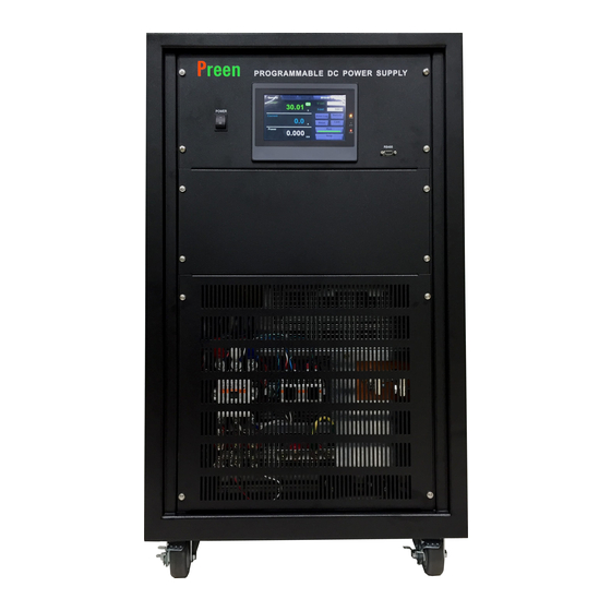
1.3 Exterior Product exterior of the ADG-P series — input voltage 380V with power level 30kW/50kW and 75kW/100kW are given as follows. (a) Front-side and back-side view, 380V, 30kW/50kW (b) Right-side and axis-side view, 380V, 30kW/50kW Figure 1.1 Product exterior of input voltage 380V with power level 30kW/50kW... - Page 15 (a) Front-side and back-side view, 380V, 75kW/100kW (b) Right-side and axis-side view, 380V, 75kW/100kW Figure 1.2 Product exterior of input voltage 380V with power level 75kW/100kW models...
- Page 16 Product exterior of the ADG-P series — input voltage 200V/208V/480V with power level 30kW/50kW and 75kW/100kW are given as follows. (a) Front-side and back-side view, 200V/208V/480V, 75kW/100kW (b) Right-side and axis-side view, 200V/208V/480V, 30kW/50kW Figure 1.3 Product exterior of input voltage 200V/208V/480V with power level...
- Page 17 (a) Front-side, back-side and right-side view, 200V/208V/480V, 75kW/1000kW Figure 1.4 Product exterior of input voltage 200V/208V/480V with power level 75kW/1000kW models...
- Page 18 This page is intentionally left blank.
-
Page 19: Installation
2 Installation 2.1 Unpacking and Check Each ADG-P series DC power supply has been carefully tested and taken every reasonable precaution to ensure that product is not damaged before shipping, however some damages might occur on the product during shipping. Please inspect the product carefully after unpacking and save all packing materials until inspection is complete. -
Page 20: Input & Output Connection
2.3 Input & Output Connection For input/output connection, please remove the front door of the product enclosure which is fixed via screws, the terminals of AC input and DC output are inside the front door. For safety requirement, ensure that the product and the DUT are switched off before connection, and screw the front door back after all connections is completed. -
Page 21: Input Connection
2.3.1 Input Connection Input installation must be done by a professional and compliant with local electrical codes. The power cable must be rated for at least 85C and its current rating must be greater than or equal to the product spec. See Section 2.3.2 for input cable selection. The AC input terminals are located as shown in Figure 2.2. - Page 22 Care must be taken to properly select wire size for the input and output of ADG-P series according to its models; refer to Table 2.1, Table 2.2 and Table 2.3. Model Input Current A/B/C ADG-P & ADG-S (30kW) 16mm 16mm ADG-P &...
-
Page 23: Output Connection
2.3.3 Output Connection The cables to the load must be sufficiently large gauges, so they will not over-heat while carrying the output current. See Section 2.3.4 for output cable selection. The location of DC output terminals is shown in Figure 2.3. Please perform the following steps for output connection. -
Page 24: Output Wire Selection
2.3.4 Output Wire Selection Output Output Model Voltage Current ADG-40-750 750A 95mm 95mm ADG-60-500 500A 95mm 95mm ADG-100-300 100V 300A 120mm 120mm ADG-200-150 200V 150A 50mm 50mm ADG-240-125 240V 125A 35mm 35mm ADG-320-94 320V 35mm 35mm 30kW ADG-400-75 400V 22mm 22mm ADG-500-60 500V... - Page 25 ADG-60-1666 1666A 150mm 150mm ADG-100-1000 100V 1000A 95mm 95mm ADG-320-312 320V 312A 70mm 70mm ADG-640-156 640V 156A 50mm 50mm ADG-1000-100 1000V 100A 35mm 35mm ADG-1600-63 1600V 16mm 16mm Table 2.3 Output cable size NOTICE For models with output voltage greater than 800V, a high-voltage cable must be used.
-
Page 26: Remote Sensing Compensation (Optional)
2.4 Remote Sensing Compensation The ADG-P series supports optional remote sensing compensation, monitoring the voltage at the load instead of the output terminals of the product, ensuring the load receives the product programming voltage by automatically compensating for the output voltage drop due to cable resistance. - Page 27 Figure 2.5 Remote sensing compensation connection to the DUT WARNING If there is a short on the leads, the CC mode will be activated and the sensing leads could burn out. If the leads are connected with reverse-polarity, the CC mode will be activated and the sensing leads could burn out.
- Page 28 This page is intentionally left blank.
-
Page 29: Local Operation
3 Local Operation The ADG-P series supports local operation via touch screen on the front panel, and remote operation via communication interface: standard RS-485, optional RS-232/ GPIB (refer to chapter 0 and 5). 3.1 Power on procedure WARNING Before turning on the product, all protective grounding terminals, extension cords, and devices connected to the product must be connected to a protective ground. - Page 30 Followed by is the General page, the default page displayed after power-on page, providing output parameters settings and measurements. The other two pages are the Function page for programming sequence: STEP and Gradual mode (refer to section 3.6), and the Setting page for system settings: time display, selection of language, output protection, communication configuration and product information (refer to section 3.7).
-
Page 31: Touch Screen Operation
3.2 Touch screen operation The ADG-P series provides an intuitive touch screen HMI for easy operation and data display. Manipulate the touch screen to enter input programming data or options by pressing the items or icons shown on the screen directly The touch screen can be disabled as well to avoid accidental touch while outputting. -
Page 32: General Page
3.3 General page The General page is the default page displayed after power-on page, used to change output parameters and simultaneously view output measurements; the parameters can also be changed when outputting. The left area displays the output measurements, press the measurement to switch from digit display to waveform simulation. - Page 33 Sets the value of output current amps. Press the white area to display the numeric keyboard or press for entry Starts the output (output ON: green light ON; output OFF: green light OFF) Stops the output (output OFF: red light ON; output ON: red light OFF) Enters the Error Log page to view the error information occurred during local operation.
-
Page 34: Constant Voltage (Cv) Mode
3.4 Constant Voltage (CV) mode When the output current to the load is lower than the set value of output current, the product will operate at the Constant Voltage mode, and the condition will be shown next to the Voltage item. Figure 3.7 CV mode Notice When setting the output voltage, the output current should also be set so that the... -
Page 35: Function Page
3.6 Function Page The ADG-P series provides programmable feature to simulate various testing conditions: the Step Mode simulates step changes of output voltage/current; while the Gradual Mode simulates continuous changes of output voltage/current. Press the icon to enter the Function Page. Select the icon to enter Step Setting page;... -
Page 36: Step Setting Page
3.6.1 Step Setting Page After entering into the Step Setting page (refer to Figure 3.10), first, select the testing mode to be programmed, the Voltage step testing (press the icon ) or the Current Step testing (press the icon ). Then, program the following parameters: output voltage/current and dwell time for each Step Set at the left area;... - Page 37 Sets the cycle time of testing (zero for infinite loop) Programs the Voltage Step Testing Programs the Current Step Testing Moves to next page Returns to the previous page Resets all settings to factory default...
-
Page 38: Step Performing Page
3.6.2 Step Performing Page In the Step Performing page, the product performs Current Step Testing/Voltage Step Testing according to each setting; refer to Figure 3.11. The left area displays the output measurements. Press the measurement to switch from digit display to waveform simulation. - Page 39 The descriptions for the items and the icons in the above figure are given as follows. Displays measurement of the output voltage in volts Displays measurement of the output current in amps Displays measurement of the output power in KW Displays the number of the ongoing Step Set Displays the voltage setting of the ongoing Step Set Displays the current setting of the ongoing Step Set...
-
Page 40: Gradual Setting Page
3.6.3 Gradual setting page After entering the Gradual Setting page (refer to Figure 3.14), first, select the testing mode to be programed, the Voltage Gradual testing (press the icon ) or the Current Gradual testing (press the icon ). Then, program the following parameters: output voltage/current and dwell time for each Gradual Set at the left area;... - Page 41 Programs the Voltage Gradual Testing Programs the Current Gradual Testing Moves to next page Returns to the previous page Resets all settings to factory default...
-
Page 42: Gradual Performing Page
3.6.4 Gradual Performing Page In the Gradual Performing page (refer to Figure 3.15), the product performs Current Gradual Testing/Voltage Gradual Testing according to each setting. The left area displays the output measurements. Press the measurement to switch from digit display to waveform simulation. The upper right area displays the output setting of the ongoing Gradual Set;... - Page 43 The descriptions for the items and the icons in the above figure are given as follows. Displays measurement of the output voltage in volts Displays measurement of the output current in amps Displays measurement of the output power in KW Displays the number of the ongoing Gradual Set Displays the start and end voltage setting of the ongoing Gradual Set in volts...
-
Page 44: Setting Page
3.7 Setting page Press the icon to enter the Setting page. Figure 3.18 Setting page The descriptions for the items and the icons in the above figure are given as follows. Enters the time setting page Enters the language setting page Enters the protection setting page Enters the communication setting page Enters the information page... -
Page 45: Time Display Setting
3.7.1 Time display setting The user is able to set the time display. Figure 3.19 Time display setting The descriptions for the items and the icons in the above figure are given as follows. Sets Year [2000-2088] Sets Month [1-12] Sets Day [1-31] Sets Hour [0-23] Sets Minute [0-59]... -
Page 46: Language Setting
3.7.2 Language setting The user is able to set interface language with three options: ENGLISH, 繁體中文 (traditional Chinese), and 简体中文 (simplified Chinese). Figure 3.20 Language setting The descriptions for the items and the icons in the above figure are given as follows. Sets English Sets Traditional Chinese Sets Simplified Chinese... -
Page 47: Protection Setting
3.7.3 Protection setting The user is able to set the protection point of overvoltage and overcurrent. The set value of protection point is within the range of 5-115% of the rated value. Refer to Section 3.8.1 and 3.8.2 for overvoltage and overcurrent protection. Figure 3.21 Protection setting The descriptions for the items and the icons in the above figure are given as follows. -
Page 48: Communication Setting
3.7.4 Communication setting The user is able to configure the communication setting for remote control and must match configuration of the PC. Refer to Section 4.1.3 for PC communication setting. Figure 3.22 Communication setting The descriptions for the items and the icons in the above figure are given as follows. Sets Modbus ID [1-255] Sets Baud Rate to 115200 (bps) Displays the data bits of the product... -
Page 49: Product Information
3.7.5 Product information The user is able to view the product information. Figure 3.23 Product information The descriptions for the items and the icons in the above figure are given as follows. Displays the model of the product Displays the rated input voltage of the product Displays the rated output voltage and current of the product... -
Page 50: Protection
3.8 Protection The ADG-P series has complete protection functions divided into two classes: the first type protection includes overvoltage and overcurrent; while the second type protection includes overtemperature and over/under input voltage. In the first class, the protection trigger point is set by the users, while the second class protection is auto detected by the system hardware protection circuit. -
Page 51: Overcurrent Protection (Ocp)
3.8.2 Overcurrent Protection (OCP) The Overcurrent Protection (OCP) function allows the product to shut down the output, if it were to exceed the set value of OCP. When OCP occurs, the condition OC displays under the Current item and the buzzer alarms. To clear the display, press the Reset icon. -
Page 52: Input Voltage Under-Voltage Protection (Vin Uvp)
3.8.4 Input Voltage Under-Voltage Protection (Vin UVP) The Input Voltage Under-Voltage Protection (Vin UVP) function allows the supply to shut down the output, if the input voltage were to be lower than the rated value. When Vin-UVP occurs, the condition Vin UV displays under the Voltage item and the buzzer alarms. -
Page 53: Error Log
3.9 Error Log The Error Log records the error information occurred during local operation, including the date, time and the error event. Figure 3.29 Error log... - Page 54 This page is intentionally left blank.
-
Page 55: Preen Program
75kW/100kW model. Figure 4.1 RS-485 DB9 connector To remotely control the ADG-P series via RS-485 interface, connect Pin 4 and Pin 6 of the DB9 connector to a PC, and ensure both side of the line are well connected. Refer to Figure 4.2 for D89 pin. -
Page 56: Notice For Installation
No Connection No Connection Figure 4.2 DB9 pin To remotely control the ADG-P series via RS-232 interface, please refer to the below picture and description. 4.1.1 Notice for installation The standard interface RS-485 only supports Modbus-RTU protocol; refer to Chapter 5. -
Page 57: Installation And Startup
Installation and Startup 4.1.2 Installation Place the CD into the CD drive and select the “Preen Program” folder with version number, such as “Preen Program V1.06.03”. Select the “setup.exe” file shown in figure below. Figure 4.3 Preen Program folder Follow the instructions to complete the installation. -
Page 58: Startup
4.1.3 Startup Click the icon on desktop or click Start→ Program→ Preen Program to start the software. The startup page is shown below. Figure 4.5 Startup page Click to enter the system setup page for communication settings with the product. - Page 59 Click to select the operational language:English, traditional Chinese or simplified Chinese. And follow the instructions below for communication setting: :Set the Connect Mode as Serial. :Set the Serial Comm Port as COM1. :Set the Modbus ID, which should be the same as the product setting. :Set the Baud Rate as 115200 (bps) After the settings is completed, to test whether the communication between the product and the PC is well connected, perform the connection test.
- Page 60 Click the icon and the connection test will run automatically. The result examples are shown below. Figure 4.8 Connection test Click the Exit to return to the system setup page after successful connection. Click OK to save the settings or Cancel to abort the settings and return to the startup page.
-
Page 61: Software Interface Operation
4.2 Software Interface Operation 4.2.1 Main page The Preen Program displays the main page as shown below when the ADG-P series is remotely connected to a PC. Figure 4.10 Main page introduction The descriptions of each numbered section in the above figure are given as follows: The operation mode: General mode/Step mode/Gradual mode. - Page 62 If the ADG-P series is not connected to a PC, the Preen Program runs in demo mode; the status is displayed at the bottom right of the main page; the icon appears and click to reconnect. Figure 4.11 Demo mode section...
-
Page 63: General Mode
4.2.2 General mode General Mode allows the user to set a set of voltage and current value for output and manually adjust the set value during outputting. Referring to Figure 4.12, there are three ways to set the output parameters: enter parameters into the field, click the up and down arrows next to the field, and click/drag the parameter bar. -
Page 64: Step Mode
4.2.3 Step Mode Step Mode allows the user to simulate Step changes of output voltage/current. Refer to Figure 4.13 and perform the followings to build a Step test: Select to perform Voltage Step testing (click the icon ) or Current Step testing (click the icon Set voltage / current and dwell time for each step in Step Set List. -
Page 65: Gradual Mode
4.2.4 Gradual Mode Gradual mode allows the user to simulate continuous voltage/current changes to execute ramp: select Voltage Grad to execute voltage ramp or Current Grad to execute current ramp. Each Gradual set forms a ramp: the set value of voltage/current of the Gradual set represents the end of the ramp, and its dwell time represents the rise/fall time of the ramp. - Page 66 When the output starts, this section displays the current cycle in Loop Times and elapsed time in Test Time as shown in Figure 4.16. The output stops when the testing cycle ends or by clicking OFF. Figure 4.16 Gradual mode (ON)
-
Page 67: Output Report
4.2.5 Output Report The Preen Program is able to provide an output measurement report regarding the setting, measurement and status during the test. Follow the steps below to save the report: Click the icon or go to Test Report→Output Report on the top menu bar. - Page 68 The parameters presented in the report can be customized: go to Test Report→ Customize Report on the menu bar. Referring to Figure 4.21, the user can select parameters to be presented and set the interval time between each recording. Figure 4.21 Customize report...
-
Page 69: Protection Settings And Output Limit Info
Figure 4.22 Path to the Protection setting Figure 4.23 Protection setting page The user is able to review the output limit of the remotely connected ADG-P series unit: go to Settings & Info→Output Limit Info on the menu bar. Figure 4.24 Output Limit Info page... -
Page 70: Modbus-Rtu Protocol
Modbus allows PC, PLC etc. (herein referred to as master) to communicate with the ADG-P series (herein referred to as slave), it will not allow data exchange between slave devices. Therefore, terminal devices will not engage the communication link at initialization but only respond to the master’s request. -
Page 71: Modbus Protocol
5.2 Modbus protocol 5.2.1 Frame When data frame reaches the terminal unit, the unit removes the data frame's header, reads the data; if there is no error, it then implements the data's task. Afterwards, the unit puts its own data with the acquired header, and sends back the frame to the sender. -
Page 72: Crc Check Field
5.2.5 CRC check field The field allows the error check by master and slave devices. Due to electrical noise and other interferences, a group of data may be changed while transmitting from one location to the other. Error Check ensures master or slave devices do not respond to the distorted data during the transmission, which enhances the system security and efficiency. -
Page 73: Message Format In Data Field
5.3 Message format in data field Below are the descriptions of the data field format. Frame status Byte count Start address (hi) Start address (lo) Register data 1 byte 1 byte 1 byte 1 byte N byte Table 5.3 5.3.1 Frame status field Included only in the response frame from the slave, the frame status field indicates whether the query frame sent by the master is accordance with the slave device’s rule. -
Page 74: Register Data Field
Start address (lo): The bottom (least significant) eight bits of a 16-bit number representing the start address. Start address (hi): The top (most significant) eight bits of a 16-bit number representing the start address. 5.3.4 Register data field Included in the query frame from the master or the response frame from the slave, the field indicates the register data that the master request to write or read in the query frame or the register data supplied in the response frame sent by the slave. -
Page 75: Transmission Example
5.4 Transmission example This chapter will illustrate how to use MODBUS protocol to control the device output or read the device measurements. Values below are represented in hex. 5.4.1 Read register (correct) The master requests to read the slave (ID 01 hex) output voltage (start address 00 00 hex). -
Page 76: Read Register (Error)
5.4.2 Read register (error) The master requests to read the slave (ID 01 hex) output voltage (start address 00 00 hex), but CRC check failed. Below is the query frame. Field name Hex value Descriptions The slave ID Function code Read the register data from the slave Byte count The byte count of the output voltage is 4 bytes... -
Page 77: Write Register (Correct)
5.4.3 Write register (correct) The master requests to write the set value of slave (ID 01 hex) output voltage (start address 00 00 hex) 100V. Below is the query frame. Field name Hex value Descriptions The slave ID Function code Write into the slave register Byte count The byte count of the Iset is 4 bytes... -
Page 78: Write Register (Error)
5.4.4 Write register (error) The master requests to write the set value of slave (ID 01 hex) output voltage (start address 00 00 hex) 800V, but it exceeds the default value. Below is the query frame. Field name Hex value Descriptions The slave ID Function code Write into the slave register... -
Page 79: Modbus Address List
5.5 Modbus address list Parameter Start address (hex) Byte count Data type Unit Single-precision Output voltage setting 00 00 floating-point Output current setting 00 04 value ⚫ Function code available: 03, 10 ⚫ Control authority (start address 00 09) should be set 01 (remote control) to permit writing. - Page 80 Parameter Start address (hex) Byte count Data type Unit Reset 00 0B Status flag Reset ⚫ Function code available: 10 ⚫ The control authority (start address 00 09) should be set to 01 (remote control) to permit writing. Parameter Start address (hex) Byte count Data type Unit...
- Page 81 This page is intentionally left blank.
-
Page 82: Calibration
6 Calibration This product allows the user to calibrate the product output and the measurement accuracy. Prepare a voltmeter, an ammeter and connecting wires beforehand for calibration. (a) Voltmeter - open circuit (b) Ammeter – short circuit Figure 6.1 Meter connection Notice The meters and wires for calibration must match the output voltage rating and output current rating of the product. - Page 83 Figure 6.2 Path to the Calibration page...
-
Page 84: Voltage Calibration
6.1 Voltage Calibration Voltage Calibration allows the user to calibrate the product output voltage with the voltmeter. Follow the steps below to perform Voltage Calibration: Connect the product to the voltmeter. Figure 6.3 Voltmeter connection Go to Setting → Calibration and press to enter the Voltage Calibration page. - Page 85 Set the output voltage value to the rated voltage, and set the output current value to 20 % of the rated current, so that the voltage could meet the set value. Figure 6.5 Sets the output value Press Run to start the output. Figure 6.6 Starts the output Wait until the measurement reading on the voltmeter is stable, and then enter the voltmeter reading into Meter value.
- Page 86 Press Update Value and the product will generate a New Base value. Figure 6.8 Generates a New Base value Confirm that the New Base value is generated. Figure 6.9 Confirms the New Base value Press Save to replace the Now Base value with the New Base value. Figure 6.10 Updates the base value...
- Page 87 Make sure the New Base value is written to the DSP. Figure 6.11 Confirms the base value is updated 10. Check whether the output current is correct with the voltmeter; if a deviation still occurs, repeat step 3 to 9 again. After completing the Voltage Calibration, press Return to go to the previous page for additional calibration or press General to go to the General page for testing.
-
Page 88: Current Calibration
6.2 Current Calibration Current Calibration allows the user to calibrate the product output voltage with the ammeter. Follow the steps below to perform Current Calibration: Connect the product to the voltmeter. Figure 6.12 Ammeter connection Go to Setting → Calibration and press to enter the Current Calibration page. - Page 89 Set the output current value to the rated current, and set the output voltage value as 10 % of the rated voltage, so that the current could meet the set value. Figure 6.14 Sets the output value Press Run to start the output. Figure 6.15 Starts the output Wait until the measurement reading on the ammeter is stable, then enter the ammeter reading into Meter value.
- Page 90 Press Update Value and the product will generate a New Base value. Figure 6.17 Generates a New Base value Confirm that the New Base value is generated. Figure 6.18 Confirms the New Base value Press Save to replace the Now Base value with the New Base value. Figure 6.19 Updates the Now Base value...
- Page 91 Make sure the New Base value is written to the DSP. Figure 6.20 Confirm the Now Base is updated 10. Check whether the output current is correct with the ammeter; if a deviation still occurs, repeat step 3 to 9 again. After completing the Current Calibration, press Return to go to the previous page for additional calibration, or press General to go to the General page for testing.
-
Page 92: Bias Calibration
6.3 Bias Calibration Bias Calibration is used to offset the deviation between the output measurement and the output setting. Follow the steps below to perform Bias Calibration: Ensure the product output is stopped. Go to Setting → Calibration and press to enter the All Bias page. - Page 93 Press Save to replace the Now Value with the New Value. Figure 6.23 Updates the Now Value Make sure the New Value is written to the DSP. Figure 6.24 Confirm the Now Value is updated After completing the All Bias Calculation, press Return to go to the previous page or press General to go to the General page for testing.
-
Page 94: Repair And Maintenance
7 Repair and Maintenance 7.1 Emergency Troubleshooting The ADG-P series DC power supply must be operated by professionals. If any abnormal conditions occur, the product will trigger protection, the output will stop and buzzer will alarm; if the protection is not triggered, the user must immediately stop the output and shut down the product. -
Page 95: Daily Maintenance
Once an abnormal condition is detected, the user should identify its root cause and eliminate the abnormal condition accordingly. If the user is unable to identify the root cause or eliminate the abnormal condition, please call Preen for technical support immediately. The earlier the abnormal condition can be removed, the longer the product life can last. -
Page 96: Monthly Maintenance
Details Object Criteria Items Period Methods 1.1. Ambient temperature must be lower than 40˚C or full load output 1. Temperature and 1. Thermometer and should be de-rated humidity hygrometer 1.2. Humidity should be complied with 2. Dust, moisture and Environment Anytime 2.
Need help?
Do you have a question about the ADG-P Series and is the answer not in the manual?
Questions and answers