
Related Manuals for Preen AFV-P Series


Summary of Contents for Preen AFV-P Series
- Page 1 AFV-P Series Programmable AC & DC Power Supply User Manual AC Power Corp. (Preen) V 1.05.01EN The information in this document is subject to change without notice. © AC Power Corp. (Preen). All rights reserved...
- Page 2 Copyright Notices. Copyright 2017 AC Power Corp. (Preen), all rights reserved. Re- production, adaptation, or translation of this document without prior written per-...
- Page 3 Preen’s AFV-P series is warranted against defects in material and workmanship for a period of two year after date of shipment. Preen agrees to repair or replace any as- sembly or component found to be defective, under normal use during this period.
- Page 4 Failure to comply with these precautions or specific WARNINGS given elsewhere in this manual will violate safety standards of design, manufacture, and intended use of the product. Preen assumes no liability for the customer‘s failure to comply with these require- ments. BEFORE APPLYING POWER Verify that the product is set to match with the power line input.
-
Page 5: Table Of Contents
Contents Table of Contents 1 GENERAL INFORMATION ....................1 1.1 Introduction ....................1 1.2 Key Features ....................2 1.3 Specifications ....................3 1.4 Exterior ......................5 1.5 Name of Parts ....................6 2 INSTALLATION ........................9 2.1 Inspection ....................... 9 2.2 User Preparation ..................... - Page 6 Contents 3.6.2 GENERAL Subpage ...................... 44 3.6.3 GENERAL Subpage with GPIB interface (optional) ............. 45 3.7 RESULTS Page ....................46 3.8 WAVE Page ..................... 47 3.9 METER Page ....................49 3.10 INFORMATION Page..................51 3.11 Protection ....................52 4 CALIBRATION ......................... 54 4.1 HI-Range Voltage 310V ...................
-
Page 7: General Information
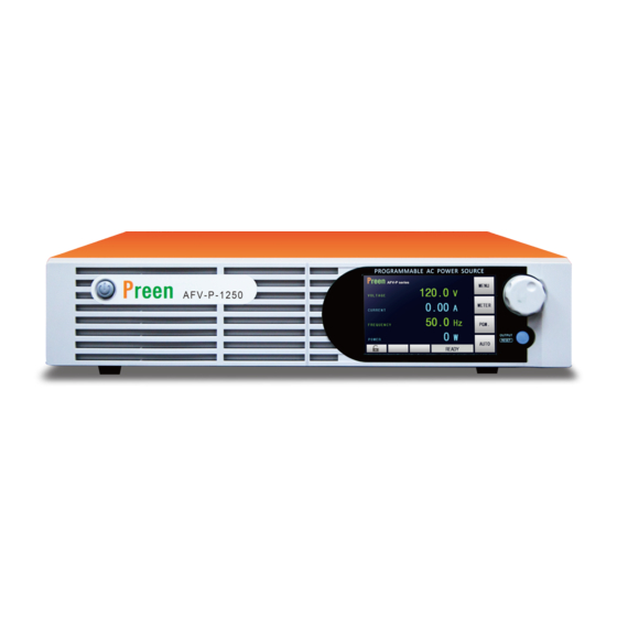
General Information 1.1 Introduction Preen’s AFV-P series is a programmable AC power supply with DC output and preci- sion measurements. This compact power supply comes in four power levels, 600VA, 1250VA, 2500VA and 5000VA, which provides stable output voltage and output fre- quency with low distortion. -
Page 8: Key Features
AFV-P Series User Manual Figure 1.2 V/I curve for the DC output of the product 1.2 Key Features A. Configuration 1. Local operation via the touch screen and the rotary knob on the front panel. 2. Remote control via RS232, RS485, Ethernet, USB or GPIB. -
Page 9: Specifications
AFV-P Series User Manual 1.3 Specifications Technical specifications of product are listed below. All specifications have been tested according to Preen’s standard test procedures. Model AFV-P-600 AFV-P-1250 AFV-P-2500 AFV-P-5000 AC Input Phase Single Input Voltage Range 98-132V /196-264V 196-264V /175-235V... - Page 10 AFV-P Series User Manual Frequency Range 15-1000Hz 0.1Hz at 40-500Hz; Frequency Accuracy 0.2Hz at 501-1000Hz Frequency Resolution 0.1Hz Hi: 1-12A/ Hi: 2-24A/ Current Range Hi: 0.05-48A Lo: 0.005-1.2A Lo: 0.005-2.4A (1% of Reading + 5 Counts), at 40-500Hz; Current Accuracy (1% of Reading + 10 Counts), at 501-1000Hz...
-
Page 11: Exterior
Product exterior of the AFV-P series are given as follows, (a) Front-side view of the AFV-P series. (b) Right-side view of the AFV-P series. Figure 1.3 Product exterior of the AFV-P series Figure 1.4 Product exterior of the AFV-P series in axis-side view... -
Page 12: Name Of Parts
AFV-P Series User Manual 1.5 Name of Parts A. Front Panel Figure 1.5 Front panel Item Name Description Power Switch Press this switch to turn on/ turn off the product. Input programming data or options by manipulating the Touch Screen touch screen to the desired one. - Page 13 AFV-P Series User Manual Figure 1.7 Rear panel (for the product models of AFV-P-1250) Figure 1.8 Rear panel (for the product models of AFV-P-2500) Figure 1.9 Rear panel (for the product model of AFV-P-5000)
- Page 14 AFV-P Series User Manual Item Name Description AC Output Socket This socket is used to output AC power to the load. Output Terminals These terminals can output AC & DC power to the load. This connector senses directly at the terminals of the load to compensate any voltage drop on the connecting cable.
-
Page 15: Installation
AFV-P Series User Manual Installation 2.1 Inspection After unpacking the product, please inspect any damage that may have occurred during the shipment. Save all packing materials in case the product has to be re- turned one day. If any damage is found, please file a claim with the carrier immediately. Do not return the product to the factory without obtaining the prior Return Merchandise Authori- zation (RMA) acceptance from Preen. -
Page 16: Output Connection
AFV-P Series User Manual Installation of the power cord to the product must be done by a professional and in accordance with local electrical codes. Figure 2.1 Input terminals 2.4 Output Connection The output terminals are located on the rear panel of the product (see Figure 2.2). -
Page 17: Remote Sense Connection
AFV-P Series User Manual 2.5 Remote Sense Connection The product supports remote sense function, which monitors the voltage at the load instead of the output terminal of the product. It ensures the delivery of accurate voltage as programmed at the load by automatically compensating the output volt- age drop over the connecting cable. -
Page 18: Power-On Procedures
AFV-P Series User Manual 2.6 Power-on Procedures WARNING Before turning on the product, all protective grounding terminals, extension cords, and devices connected to the product must be connected to a protective ground. Any interruption of the protective ground will cause a potential shock hazard that could result in personal injury. -
Page 19: Product Handle Installation
AFV-P Series User Manual 2.7 Product Handle Installation To install the handles to the right-side and the left-side of the product, please refer to the Figure 2.7 to fix the handles to the product with eight screws. Figure 2.7 Product handle 2.8 Interface Card Installation... -
Page 20: Rs232/Rs485 9-Pin D-Type Connector
AFV-P Series User Manual 2.8.1 RS232/RS485 9-Pin D-Type Connector To remotely control the product output via the interface RS232 or RS485, please connect a computer with the product via the RS232/RS485 9-pin D-type connector according to the following instructions. The definition for the pins of the RS232/RS485 9-pin D-type female connector is giv- en as follows: Pin NO. - Page 21 AFV-P Series User Manual The definition for the pins of the PLC remote output female connector is given as follows: Pin NO. Definition Pass Pass Fail Fail Processing Processing Figure 2.11 PLC remote output No Connection female connector No Connection...
-
Page 22: Local Operation
AFV-P Series User Manual Local Operation 3.1 General The product can support local operation or remote operation. The remote operation enabled via complete communication interfaces, such as RS232, RS485, Ethernet, USB or GPIB will be described in Chapter 8. In this section, the local operation ena- bled via the touch screen and the rotary knob on the front panel will be described. - Page 23 AFV-P Series User Manual Figure 3.2 Virtual numeric and decimal keys B. Rotary Knob Turn the rotary knob on the front panel to move the cursor shown on the touch screen, and press the rotary knob to choose the desired item. After choosing the de- sired item, continue to turn the rotary knob to set value, and then press the rotary knob to confirm.
-
Page 24: Main Page
AFV-P Series User Manual 3.3 MAIN Page When users turn on the product, the touch screen shows the MAIN page after the power-on procedures. The MAIN page shows the output settings and the measure- ment readings of the product output. Users can set output value by using the touch screen or the rotary knob (refer to Subsection 3.2), and then press the output &... -
Page 25: Output Voltage Range
AFV-P Series User Manual : Press to enter into the METER page. : Press to enter into the PROGRAMMABLE page. : Press to set the output voltage range, with two options of HIGH and AUTO. : Shown the status of the output or the error code. -
Page 26: Menu Page
AFV-P Series User Manual Figure 3.6 Set the output voltage range from HIGH to AUTO 3.4 MENU Page If the MAIN page is shown on the touch screen, users can press the icon enter into the MENU page. Please see the following figures, Figure 3.7 MENU page 1... -
Page 27: Settings Page
AFV-P Series User Manual : Press to enter into the METER page. : Press to enter into the INFORMATION page. : Press to return to the MAIN page. : Press to return to the previous page. : Press to move to the previous page of the MENU page. - Page 28 AFV-P Series User Manual Figure 3.10 TESTING subpage 3 & 4 (ADVANCED mode) The description for the items and the icons at the TESTING subpage (ADVANCED mode) are given as follows: : Press to set the operational mode, with two options of ADVANCE and BASIC.
- Page 29 AFV-P Series User Manual : Press to enable/disable the consecutive step feature, with two options of ON and OFF. : Press to enable/disable the synchronized signal, with three options of EVENT, OFF and ON. : Press to move to the previous page of the TESTING subpage.
- Page 30 AFV-P Series User Manual 3.5.1.1 Output Mode (AC or DC) At the TESTING subpage 1 (ADVANCED mode), users are allowed to set the output mode with two options of AC and DC, so as to fit their application. Then, the MAIN page will change correspondingly according to the output mode.
- Page 31 AFV-P Series User Manual Figure 3.13 Set the output mode from AC to DC (ADVANCED mode) 3.5.1.2 Over Current Foldback At the TESTING subpage 1 (ADVANCED mode), users are allowed to enable the over current foldback. When the output current exceeds the maximum rated current, and the over current foldback is enabled, the product can automatically control the out- put voltage to maintain the output current at the maximum rated current.
- Page 32 AFV-P Series User Manual numeric keys are given as below: 1. Press the item to use the virtual numeric keys to set the value of 90. 2. Press the icon to confirm. Figure 3.15 Set the start angle from 0 to 90 (ADVANCED mode) Secondly, the procedures of setting the end angle from 0...
- Page 33 AFV-P Series User Manual 3.5.1.4 Power-on Status At the TESTING subpage 2 (ADVANCED mode), users are allowed to set the power-on status with three options of OFF, ON and LAST. OFF indicates that the output is off after turning on the product; ON indicates that the output is on after turning on the product;...
- Page 34 AFV-P Series User Manual Figure 3.18 Three options of the synchronized signal (ADVANCED mode) 3.5.1.6 Voltage Sense There are two options for users to set the voltmeter point: INT and EXT, and the de- fault option is INT. INT indicates that the voltmeter point is located at the terminals “N”...
- Page 35 AFV-P Series User Manual NOTICE When the voltmeter point is set to be EXT, but the terminals “S ” and “S ” are not connected to the load, the Low Voltage Protection (LVP) will be triggered after the output is on.
- Page 36 AFV-P Series User Manual B. Consecutive Step Feature There are two options of the consecutive step feature: ON and OFF, and the default option is ON. ON indicates that each Step and Memory Set will be continuously per- formed without any HINT page when the PROGRAMMABLE feature is performed;...
-
Page 37: Testing Subpage (Basic Mode)
AFV-P Series User Manual 3.5.2 TESTING Subpage (BASIC Mode) If the operational mode is set to be the BASIC mode, the TESTING subpage at the BASIC mode will be shown on the touch screen after entering into the SETTINGS page. - Page 38 AFV-P Series User Manual : Press to set the end angle, with options from 0 to 359. : Press to set the power-on status, with three options of OFF, ON and LAST. : Press to set the voltmeter point, with two options of INT and EXT.
- Page 39 AFV-P Series User Manual 2. Press the icon to confirm. Figure 3.26 Set the output mode from AC to DC (BASIC mode) 3.5.2.2 Over Current Foldback At the TESTING subpage 1 (BASIC mode), users are allowed to enable the over cur- rent foldback.
- Page 40 AFV-P Series User Manual start angle and the end angle) of the output waveform. Firstly, the procedures of setting the start angle from 0 to 90 by using the virtual numeric keys are given as below: 1. Press the item to use the virtual numeric keys to set the value of 90.
- Page 41 AFV-P Series User Manual 3.5.2.4 Power-on Status At the TESTING subpage 2 (BASIC mode), users are allowed to set the power-on sta- tus with three options of OFF, ON and LAST. OFF indicates that the output is off after turning on the product; ON indicates that the output is on after turning on the prod- uct;...
- Page 42 AFV-P Series User Manual quency and the minimum rated frequency), the product can automatically control the setting value of the output frequency to maintain the output frequency at the rated frequency. 3.5.2.7 Synchronized Signal At the TESTING subpage 4 (BASIC mode), users are allowed to enable the synchro- nized signal with three options of EVENT, OFF and ON, and the default option is EVENT.
-
Page 43: System Subpage
AFV-P Series User Manual Figure 3.32 Set the voltmeter point from INT to EXT (BASIC mode) NOTICE When the voltmeter point is set to be EXT, but the terminals “S ” and “S ” are not connected to the load, the Low Voltage Protection (LVP) will be triggered after the output is on. - Page 44 AFV-P Series User Manual Figure 3.34 SYSTEM subpage 3 The description for the items and the icons at the SYSTEM subpage are given as fol- lows, : Press to set the operational language, with four op- tions of ENGLISH, 繁體中文 and 简体中文.
- Page 45 AFV-P Series User Manual 3.5.3.1 Operational Language At the SYSTEM subpage 1, users are allowed to set the operational language with four options of ENGLISH, 繁體中文 and 简体中文, and the default operational language is ENGLISH. ENGLISH indicates English; 繁體中文 indicates Traditional Chinese;...
- Page 46 AFV-P Series User Manual Figure 3.36 Set the alarm volume from 5 to 9 3.5.3.3 Backlight Level At the SYSTEM subpage 1, users are allowed to set the backlight level of the touch screen with options from 0 to 9 by using the touch screen and the rotary knob (refer to Subsection 3.2), and the default backlight level is 9.
- Page 47 AFV-P Series User Manual P/F indicates that the product will display whether each Step Loop is pass the output test or not at the RESULTS page after performing the PROGRAMMABLE feature (refer to Subsection 3.5.5). Figure 3.38 Three options of the RESULTS feature.
- Page 48 AFV-P Series User Manual low: 1. Press the item twice to switch the icon status to YES. 2. Press the icon to confirm and reset the product. Figure 3.40 Reset the product to the default settings...
-
Page 49: Communication Page
AFV-P Series User Manual 3.6 COMMUNICATION Page If the MENU page is shown on the touch screen, users can press the icon enter into the COMMUNICATION page, and the COMMUNICATION page includes two subpages: the ETHERNET subpage and the GENERAL subpage. -
Page 50: General Subpage
AFV-P Series User Manual : Press to set the MAC address under the MANUAL mode. : Press to set the Ethernet port under the MANUAL mode. : Press to move to the previous page of the ETHERNET subpage. : Press to move to the next page of the ETHERNET subpage. -
Page 51: General Subpage With Gpib Interface (Optional)
AFV-P Series User Manual 255. : Press to set the Baud rate, with five options of 9600bps, 19200bps, 38400bps, 57600bps and 115200bps. : Press to move to the previous page of the GENERAL subpage. : Press to move to the next page of the GENERAL subpage. -
Page 52: Results Page
AFV-P Series User Manual 3.7 RESULTS Page If the MENU page is shown on the touch screen, users can press the icon enter into the RESULTS page. Please see the following figures, Figure 3.44 RESULTS page The description for the icons at the RESULTS page are given as follows, : Press to see the settings of the desired Step of the Memory Set. -
Page 53: Wave Page
AFV-P Series User Manual 3.8 WAVE Page If the MENU page is shown on the touch screen, users can press the icon enter into the WAVE page. Please see the following figures, Figure 3.45 WAVE page when the product output is off Figure 3.46 WAVE page when the product output is on... - Page 54 AFV-P Series User Manual The description for the icons at the WAVE page are given as follows, : Press to set the displaying scale of the output voltage, with two options of 40V and 200V per division. : Press to set the display scale of the time, with six options of 1ms, 2ms, 4ms, 10ms, 100s, 200s and 400s per division.
-
Page 55: Meter Page
AFV-P Series User Manual 3.9 METER Page If the MENU page is shown on the touch screen, users can press the icon enter into the METER page. Please see the following figures, Figure 3.48 METER page when the product output is on Figure 3.49 METER page when the PROGRAMMABLE feature is performed... - Page 56 AFV-P Series User Manual The description for the items and the icons at the METER page are given as follows, : Show the measurement reading of the output volt- age. : Show the measurement reading of the output cur- rent.
-
Page 57: Information Page
AFV-P Series User Manual 3.10 INFORMATION Page If the MENU page is shown on the touch screen, users can press the icon enter into the INFORMATION page. Please see the following figures: Figure 3.51 INFORMATION page The description for the items at the INFORMATION page are given as follows: : Show the producer of the product. -
Page 58: Protection
AFV-P Series User Manual 3.11 Protection The product provides complete protection for OVP, LVP, OCP, OPP, OTP, RCP, Fan Fail and AMP Fail. When the protection is triggered, the product will immediately stop the product output, and show the error code corresponding to the protection condi- tion on the touch screen. - Page 59 AFV-P Series User Manual Protection 2. High environmental tem- for product ventilation perature. 2. Use the vacuum cleaner to clean the air inlet 3. Install the product on the place with environmental temperature not exceeding 40C. Problems of the current...
-
Page 60: Calibration
AFV-P Series User Manual Calibration The product provides a simple way to calibrate the product output and measurement accuracy without opening cover. Users can perform the calibration according to the procedures given as follows step by step. A voltage meter, a current meter and suita- ble load are needed while performing the calibration procedures. - Page 61 AFV-P Series User Manual Figure 4.3 CALIBRATION pages 1 & 2 Figure 4.4 CALIBRATION page 3 The description for the items at the CALIBRATION page are given as follows, : Press to enter into the page which calibrates the HI-Range voltage 310V.
-
Page 62: Hi-Range Voltage 310V
AFV-P Series User Manual LO-Range RMS current. : Press to enter into the page which calibrates the peak current. : Press to enter into the page which calibrate the output socket current (specialize for the product model of AFV-P-5000). : Press to move to the previous page of the CALIBRATION page. -
Page 63: Lo-Range Voltage 155V
AFV-P Series User Manual Figure 4.5 Enter into the page which calibrates the HI-Range voltage 310V Figure 4.6 Enable the calibration of the HI-Range voltage 310V 4.2 LO-Range Voltage 155V At the CALIBRATION page 1, users are allowed to enter into the page which calibrates the LO-Range voltage 155V. -
Page 64: Hi-Range Voltage 60V
AFV-P Series User Manual NOTICE Before calibrating the LO-Range voltage 155V, the load shall be temporally re- moved from the product to avoid a potential electric shock. Figure 4.7 Enter into the page which calibrates the LO-Range voltage 155V Figure 4.8 Enable the calibration of the LO-Range voltage 155V 4.3 HI-Range Voltage 60V... -
Page 65: Lo-Range Voltage 60V
AFV-P Series User Manual ment reading shown on the voltage meter. 5. Press the rotary knob to confirm and finish the calibration. NOTICE Before calibrating the HI-Range voltage 60V, the load shall be temporally re- moved from the product to avoid a potential electric shock. - Page 66 AFV-P Series User Manual 4. Use the rotary knob to adjust the product output until the measurement read- ing of the output voltage shown on the touch screen is closed to the measure- ment reading shown on the voltage meter.
- Page 67 AFV-P Series User Manual NOTICE Before calibrating the LO-Range voltage 60V, the load shall be temporally re- moved from the product to avoid a potential electric shock. Figure 4.11 Enter into the page which calibrates the LO-Range voltage 60V Figure 4.12 Enable the calibration of the LO-Range voltage 60V...
-
Page 68: Hi-Range Rms Current
AFV-P Series User Manual 4.5 HI-Range RMS Current At the CALIBRATION page 2, users are allowed to enter into the page which calibrates the HI-Range RMS current. The procedures of calibrating the HI-Range RMS current are given as below: 1. Press the item repeatedly to enter into the page which calibrates the HI-Range RMS current (refer to Figure 4.13). -
Page 69: Lo-Range Rms Current
AFV-P Series User Manual Figure 4.14 Enable the calibration of the HI-Range RMS current 4.6 LO-Range RMS Current At the CALIBRATION page 2, users are allowed to enter into the page which calibrates the LO-Range RMS current. The procedures of calibrating the LO-Range RMS current are given as below: 1. -
Page 70: Peak Current
AFV-P Series User Manual Figure 4.15 Enter into the page which calibrates the LO-Range RMS current Figure 4.16 Enable the calibration of the LO-Range RMS current 4.7 Peak Current At the CALIBRATION page 3, users are allowed to enter into the page which calibrates the peak current. - Page 71 AFV-P Series User Manual NOTICE The definition of the suitable load for calibrating the peak current are given as follows, and the suitable load shall be resistive load. Model Resistive Value Rated Power AFV-P-600 20Ω 500W AFV-P-1250 10Ω 1000W AFV-P-2500 5Ω...
-
Page 72: Output Socket Current (Specialize For Afv-P-5000)
AFV-P Series User Manual 4.8 Output Socket Current (Specialize for AFV-P-5000) At the CALIBRATION page 3, users are allowed to enter into the page which calibrates the output socket current. Since the maximum output current corresponding to the product model of AFV-P-5000 is 40A, which exceeds the maximum rated current of the AC output socket (that is, 20A), the calibration of the output socket current is necessary to protect the AC output socket from over current damage. - Page 73 AFV-P Series User Manual Figure 4.20 Enable the calibration of the output socket current...
-
Page 74: Programmable Features
AFV-P Series User Manual PROGRAMMABLE Features 5.1 General The product can not only provide the steady output voltage and output frequency, but also provide several powerful functions to simulate all kinds of power line condi- tions and disturbance. Users can make the output change according to the setting value step by step via the STEP feature (refer to Subsection 5.2), or make the output... - Page 75 AFV-P Series User Manual Figure 5.3 PROGRAMMABLE page when the Memory Loop is off Figure 5.4 PROGRAMMABLE page when the Memory Loop is on The description for the icons at the PROGRAMMABLE page are given as follows, : Press to set the start number of the Memory Loop, with options from 1 to 50.
- Page 76 AFV-P Series User Manual : Press to move to the next page of PROGRAMMABLE page to select the desired Memory Set. B. Memory Loop At the PROGRAMMABLE page, users are allowed to set the Memory Loop, and 50 Memory Sets are supported for simulating power line conditions and disturbance.
- Page 77 AFV-P Series User Manual When the Memory Loop is performed, the following page will be shown on the touch screen, Figure 5.5 PROGRAMMABLE page when the Memory Loop is performed...
-
Page 78: Step Feature
AFV-P Series User Manual 5.2 STEP Feature A. STEP Page At the PROGRAMMABLE page, users are allowed to enable the STEP feature which makes the output change step by step at the STEP page, and 24 STEPs for each Memory Set are supported. To enter into the STEP page of the desired Memory Set, users can press the icon of the desired Memory Set. - Page 79 AFV-P Series User Manual from 1 to 24. : Press to set the end number of the Step Loop, with options from 1 to 24. : Press to set the Step Loop times, with options from 1 to 999. : Press to enter into the subpage of the desired Step.
- Page 80 AFV-P Series User Manual For example, when the start number of the Step Loop is 3, the end number of the Step Loop is 7, and the Step Loop times is 10, but the Step 5 is disabled, the Step Loop will be sequentially performed from the Step 3 to the Step 7 except the Step 5 and repeated 10 times.
- Page 81 AFV-P Series User Manual B. STEP Feature Example To illustrate the STEP feature, the figures shown below are the example of setting the STEP feature for the Step 1 & 2 & 3 and the output waveform corresponding to this example.
- Page 82 AFV-P Series User Manual C. GENERAL Subpage When the STEP page is shown on the touch screen, users can press the icon to enter into the subpages of the Step 1. Similarly, users can press the icon to enter into the subpages of the Step 2, and so on.
- Page 83 AFV-P Series User Manual desired Step, with three options from SECOND, MINUTE and HOUR. : Press to reset the desired Step to the default set- tings. : Press to reset all Steps of the desired Memory Set to the default settings.
- Page 84 AFV-P Series User Manual E. LIMITS Subpage After pressing the icon at the STEP page, the GENERAL subpage will be shown on the touch screen in advance. Then users can press the icon to enter into the LIMITS subpage, and enable the LIMITS feature to perform the out- put test for the desired Step.
- Page 85 AFV-P Series User Manual Figure 5.17 LIMITS subpage 5 The description for the items and the icons at the GENERAL subpage of the Step 1 are given as follows, : Press to set the delay time to perform the LIMITS feature, with options from 0.5s to 999.9s, and the default option is 0.5s.
- Page 86 AFV-P Series User Manual desired Step, with options which are similar to that of the maximum rated peak current. : Press to set the maximum rated power for the desired Step, with options from 1W to 500W for AFV-P-600; from 1W to 1000W for AFV-P-1250;...
- Page 87 AFV-P Series User Manual reactive power less than 1VAR, the output of the maximum rated reactive power will be disabled, and this icon status will be OFF. : Press to set the minimum rated reactive power for the desired Step, with options which are similar to that of the maximum rated reactive power.
-
Page 88: Ramp Feature
AFV-P Series User Manual 5.3 RAMP Feature A. RAMP Page At the RAMP subpage, users are allowed to enable the RAMP feature which makes the output change according to the setting slew rate. Please see the following fig- ures, Figure 5.18 RAMP subpage 1 & 2... - Page 89 AFV-P Series User Manual : Press to move to the previous page of the RAMP subpage. : Press to move to the next page of RAMP subpage. B. RAMP Feature Example To illustrate the RAMP feature, the figures shown below are the example of setting the RAMP feature for the Step 1 and the output waveform corresponding to this example.
-
Page 90: Transient Feature
AFV-P Series User Manual 5.4 TRANSIENT Feature A. TRANSIENT Page If the STEP page is shown on the touch screen, users can press the item enter into the TRANSIENT page, and users are allowed to enable the TRANSIENT fea- ture which makes the output change for a specific period of time at the TRANSIENT page. - Page 91 AFV-P Series User Manual to 359. : Press to set the Transient dwell time, with options from 0.5ms to 999.9ms. : Press to set the Transient cycle times, with options from 1 to 9999. While setting the Transient cycle times to 0, the Transient feature will be performed every cycle once.
- Page 92 AFV-P Series User Manual Figure 5.25 Output waveform corresponding to the example above...
-
Page 93: Theory Of Operation
AFV-P Series User Manual Theory of Operation The product mainly consists of 8 function blocks, and each of the function blocks has its own specific function. The function blocks of the product are given as below, Figure 6.1 Function block of the product... -
Page 94: Remote Operation
AFV-P Series User Manual Remote Operation For remotely control the product via the remote control software released by Preen, please refer to the file “READ ME” in the attached CD-ROM which is encased with the product, so as to install the corresponding remote control software and device driver. - Page 95 AFV-P Series User Manual Figure 7.2 User interface of the remote control software when the product output is on...
-
Page 96: Remote Control Software: General Mode
AFV-P Series User Manual 7.2 Remote Control Software: General Mode After enabling the remote control software, the general mode of the remote control software will be shown in advance. Please see the following figure, Figure 7.3 Remote control software: general mode... - Page 97 AFV-P Series User Manual software is similar to the description for the SETTINGS page mentioned ac- cording to Subsection 3.5. 15) Click to exit the remote control software. Figure 7.4 Show the measurement readings of the product output Figure 7.5 Select the desired file form of the product output report...
- Page 98 AFV-P Series User Manual Figure 7.6 Setting page of the remote control software...
-
Page 99: Remote Control Software: Program Mode
AFV-P Series User Manual 7.3 Remote Control Software: Program Mode To enter into the program mode of the remote control software, please click the icon “Program Mode” which is mark in red square below, Figure 7.7 Click the icon “Program Mode” to enter into the program mode Figure 7.8 Remote control software: program mode. - Page 100 AFV-P Series User Manual the PROGRAMMABLE page mentioned according to Section 5. 2) Click to enable/disable the Memory Loop. 3) Use to set the start number of the Memory Loop. 4) Use to set the end number of the Memory Loop.
-
Page 101: Remote Control Software: Additional Features
AFV-P Series User Manual 7.4 Remote Control Software: Additional Features A. Reset to Default Settings To reset the setting of the remote control software to the default setting, please do the following procedures step by step, 1 Click the item “File”, and then click the item “Load Default” (see Figure 7.11). - Page 102 AFV-P Series User Manual Figure 7.12 Select the desired settings to reset B. Build Customized Product Output Report To build the customized product output report, please do the following procedures step by step, 1 Click the item “Test Report”, and then click the item “Customize Report” (see Figure 7.13).
- Page 103 AFV-P Series User Manual Figure 7.14 Select the desired items to show on the product output report...
Need help?
Do you have a question about the AFV-P Series and is the answer not in the manual?
Questions and answers