Advertisement
Quick Links
Tool Required
5/32" Hex Allen Key
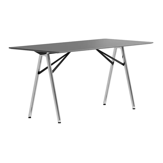
GSD Table
Assembly Instructions
1
Interlock the aluminum table legs (x2) by positioning
the bosses in line with their corresponding pockets. Pull
and hold the legs towards each other.
3
Screw the glide (x4) into each aluminum table leg.
5
Using the 5/32" hex key, fasten the channel to the
aluminum legs with with 1/4"-20 x 1/2" button head cap
screw (x4).
Hardware Included
1/4-20 x 3/4"
1/4-20 x 1"
Button head cap screw
Button head cap
(x6) per 71 & 86 inch table
screw (x2)
(x8) per 102 inch table
1/4-20 x 1/2"
1/4-20 x 3/4"
Button head cap screw
Flat head cap screw
(x2) Bar & Counter
(x4) Conference
(x8) Bar & Counter
2
Place the aluminum leg sub assemblies at each
end of the channel. Using the 5/32" hex key, install
the 1/4"-20 x 1" button head cap screw (x2).
Bar & Counter Table Only
4
Overlap table brace (x2) and place into aluminum legs. Using
the 5/32" hex key, install the 1/4"-20 x 1/2" button head
cap screw (x4). Attach brace (x2) to the channel with the
1/4"-20 x 3/4" flat head screw (x2) using the 5/32" hex key.
6
Using the 5/32" hex key, fasten the table base to the
table top with 1/4 - 20 x 3/4" button head cap screw
and washer (x6) or (x8).
1
Washer
Glide
(x6) per 71 & 86 inch table
(x4)
(x8) per 102 inch table
keilhauer.com
Advertisement

Subscribe to Our Youtube Channel
Summary of Contents for keilhauer GSD
- Page 1 (x8) per 102 inch table (x4) Conference (x8) per 102 inch table (x8) Bar & Counter GSD Table Assembly Instructions Interlock the aluminum table legs (x2) by positioning Place the aluminum leg sub assemblies at each the bosses in line with their corresponding pockets. Pull end of the channel.
- Page 2 Press the table end cap (x2) over each end of the channel. Place the assembled table in it’s final position. GSD Power Table Assembly Instructions Feed the power cord through the cut out and install the Using the 5/32” hex key, fasten the table base to the table power box (x1).
- Page 3 (x4) Bar & Counter GSD Table Ganging Instructions See GSD Table Assembly Instructions for General Assembly Place the aluminum leg sub assembly on the ganging Screw the glide (x2) into each aluminum table leg. channel. Using the 5/32” hex key, install the 1/4”-20 x 1”...
- Page 4 Button head cap screw (x6) per 71 & 86 inch table (x8) per 102 inch table (x6) per 71 & 86 inch table (x8) per 102 inch table GSD Table Ganging Instructions Underside of table Underside of table shown. shown.


Need help?
Do you have a question about the GSD and is the answer not in the manual?
Questions and answers