
Subscribe to Our Youtube Channel
Related Manuals for Designers Fountain 54GP2L5-VBG


Summary of Contents for Designers Fountain 54GP2L5-VBG
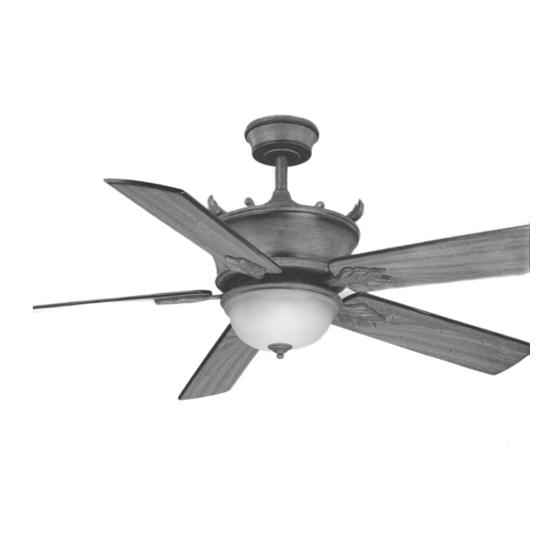
- Page 1 Distinctive Lighting and Ceiling Fans CEILING FAN OWNER'S MANUAL MODEL: 54GP2L5-VBG READ AND SAVE THESE INSTRUCTIONS FOR CEILING FAN PARTS AND SERVICE, CALL 1-877-902-5588 FAN RATING AC 120V. 60Hz UL LISTED MODEL : AC-416...
-
Page 2: Safety Rules
1. SAFETY RULES 1. To reduce the risk of electric shock, 7. To operate the reverse function on this insure electricity has been turned off fan, press the reverse button while the at the circuit breaker or fuse box fan is running. before beginning. -
Page 3: Tools And Materials Required
2. TOOLS AND MATERIALS REQUIRED Philips screw driver Blade screw driver 11 mm wrench Step ladder Wire cutters 3. PACKAGE CONTENTS Unpack your fan and check the contents. You should have the following items: a. Blade set (5) b. Hanger bracket assembly c. -
Page 4: Mounting Options
4. MOUNTING OPTIONS If there isn't an existing UL listed mounting box, then read the following instructions. Disconnect the power by removing fuses or turning off circuit breakers. Secure the outlet box directly to the Outlet box building structure. Use appropriate fasteners and building materials. -
Page 5: Hanging The Fan
5. HANGING THE FAN Hanger bracket REMEMBER to turn off the power. Follow the steps below to hang your fan properly: Ceiling canopy Step 1. Remove the decorative canopy bottom cover from the canopy by turning the cover counter clockwise.(Fig. 5) Canopy Step 2. -
Page 6: Make The Electric Connections
CHANGING THE DOWNROD (OPTIONAL) Cross pin NOTE: Your fan comes with a 6" downrod attached to the hanger ball. In addition you have been provided with a 4" Hanger downrod to use if desired. If you choose to ball Set screw use the 4"... -
Page 7: Finishing The Installation
Step 3. (Fig. 12) Receiver to House Supply Wires Electrical Connections: Connect the black (hot) wire from the ceiling to the Outlet box black wire marked "AC in L" from the White (neutral) receiver. Connect the white (neutral) wire Black (hot) Green or bare from the ceiling to the white wire marked copper (ground) -
Page 8: Attaching The Fan Blades
8. ATTACHING THE FAN BLADES Caution: Remove 5 rubber packing mounts and discard before installation. Step 1 Attach the blade to the blade bracket using the screws and fiber washers as shown in Figure 14. Start screw into bracket. Repeat for the two remaining screws. -
Page 9: Installing The Light Kit
10. INSTALLING THE LIGHT KIT NOTE: Before starting installation, disconnect the power by turning off the circuit breaker or removing the fuse at fuse box. Turning power off using the fan switch is not sufficient to prevent electric shock. 1. Raise and hold the light kit close to the mounting plate and proceed to do the wire connections. -
Page 10: Installing The Battery
12. INSTALLING THE BATTERY Install 9 volt battery (included), to prevent damage to transmitter, remove the battery if not used for long periods. (Fig. 13. OPERATING INSTRUCTIONS Restore power to ceiling fan and test for Figure 18 proper operation. A. HI, MED, and LOW buttons: These three buttons are used to set the fan speed as follows: HI= high speed... - Page 11 Speed settings for warm or cool weather depend on factors such as the room size. Ceiling height, number of fans and so on. NOTE: To operate the reverse function on this fan, press the reverse button while the fan is running. Warm weather - (Forward) A downward airflow creates a cooling effect as shown in Fig.
-
Page 12: Troubleshooting
14. TROUBLESHOOTING Problem Solution Fan will not start. 1. Check circuit fuses or breakers. 2. Check line wire connections to the fan and switch wire connections in the switch housing. CAUTION: Make sure main power is off. 3. Check to make sure the dip switches from the transmitter and receiver are set to the same frequency.
Need help?
Do you have a question about the 54GP2L5-VBG and is the answer not in the manual?
Questions and answers