
Related Manuals for Raycap PowerPlus RDIDC-100-3R-1U Series


Summary of Contents for Raycap PowerPlus RDIDC-100-3R-1U Series
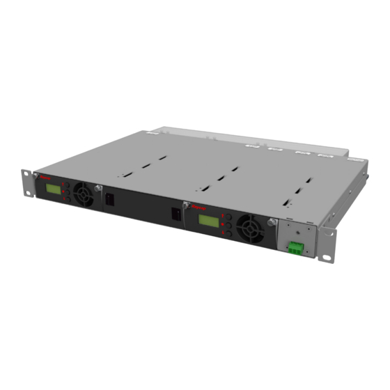
- Page 1 PowerPlus RDIDC-100-3R-1U-X INSTALLATION INSTRUCTION & OPERATION MANUAL INSTALLATION INSTRUCTION & OPERATION MANUAL PowerPlus RDIDC-100-3R-1U-X PowerPlus RDIDC-100-3R-1U-2 PowerPlus RDIDC-100-3R-1U-1 www.raycap.com...
-
Page 3: Table Of Contents
System Low Temperature ........................23 10.8 Module DC/DC Converter Failure ....................23 10.9 Module DC/DC Converter Communication Failure .................23 11. Appendix ..............................24 © Raycap | All rights reserved. • (320-1674) | Rev.A www.raycap.com Page 3 of 28 Scan QR for Complete Installation Instructions:... -
Page 4: Copyright
Disclaimer The information in this document is subject to change without notice and describes only the product defined in the introduction of this documentation. This documentation is intended for the use of Raycap customers only for the purposes of the agreement under which the document is submitted, and no part may be used, reproduced, modified or transmitted in any form or means without the prior written permission of Raycap. The documentation has been prepared to be used by professional and properly trained personnel, and the customer assumes full responsibility when using it. -
Page 5: Introduction
® electrical protection at the RRH and BBU. PowerPlus is Raycap’s solution for power transmission to the RRH units of a DAS Telecommunication site. PowerPlus is a system installed at the PSU output that boosts the voltage at the base of a cellular site to overcome the voltage drop on the DC power cables that provide power to the RRHs. -
Page 6: Mounting
You will need 1U vertical space. The unit ships with a Rack Extension Kit to mount into a 23" rack. Mount the unit on the rack. © Raycap | All rights reserved. • (320-1674) | Rev.A www.raycap.com Page 6 of 28... - Page 7 2.14 Mounting Position A3 Mounting Position A4 Release the 4 push pins and remove touch guard as shown below. © Raycap | All rights reserved. • (320-1674) | Rev.A www.raycap.com Page 7 of 28 Scan QR for Complete Installation Instructions:...
-
Page 8: General Description
The PowerPlus RDIDC-100-3-1U-X system is composed of a mounting rack and up to three pluggable modules. • The voltage output of each module is connected to a Raycap Power Distribution Unit (PDU) model RDIDC-9052-PDU-48. © Raycap | All rights reserved. -
Page 9: System Topology
PowerPlus RDIDC-100-3R-1U-X INSTALLATION INSTRUCTION & OPERATION MANUAL System Topology -48VDC -48VDC -48VDC OUT 1 Unused OUT 2 © Raycap | All rights reserved. • (320-1674) | Rev.A www.raycap.com Page 9 of 28 Scan QR for Complete Installation Instructions:... -
Page 10: Installation Configuration
PowerPlus RDIDC-100-3R-1U-X INSTALLATION INSTRUCTION & OPERATION MANUAL Installation Configuration -48VDC OUT 2 -48VDC Unused -48VDC OUT 1 RTN OUT PowerPlus RDIDC-100-3-1U-X system configuration © Raycap | All rights reserved. • (320-1674) | Rev.A www.raycap.com Page 10 of 28 Scan QR for Complete Installation Instructions:... -
Page 11: Single Module Configuration
Use #6 AWG -48V Return -48V Return Use #6 AWG copper RDIDC-9052-PDU-48 copper wire wire for ground for ground © Raycap | All rights reserved. • (320-1674) | Rev.A www.raycap.com Page 11 of 28 Scan QR for Complete Installation Instructions:... -
Page 12: Dual Module Configuration
Use #6 AWG -48V Return -48V Return Use #6 AWG copper RDIDC-9052-PDU-48 copper wire wire for ground for ground © Raycap | All rights reserved. • (320-1674) | Rev.A www.raycap.com Page 12 of 28 Scan QR for Complete Installation Instructions:... -
Page 13: System Management
• All modules will display the input and output voltage of the system. The Primary module is indicated by an “P” character which is located at the end of the input voltage value (first line of the display). Primary Secondary © Raycap | All rights reserved. • (320-1674) | Rev.A www.raycap.com Page 13 of 28 Scan QR for Complete Installation Instructions:... -
Page 14: Module Failure
When this occurs, the current Primary module will transfer output voltage to the new module. The new module will be configured as a new Secondary module. • The alarm will disappear after pressing the ‘ENTER’ button on the current Primary module for more than 3 seconds. © Raycap | All rights reserved. • (320-1674) | Rev.A www.raycap.com Page 14 of 28... -
Page 15: Modules
Unscrew the thumb screws on both sides of module. • Release the side levers. • Pull out the device. © Raycap | All rights reserved. • (320-1674) | Rev.A www.raycap.com Page 15 of 28 Scan QR for Complete Installation Instructions:... -
Page 16: Cold Module Replacement
• If there is a cold module installation in open slot(s), then the system will prompt for initial settings during power ON. © Raycap | All rights reserved. • (320-1674) | Rev.A www.raycap.com Page 16 of 28... -
Page 17: Module Settings
• The Primary module is selected by pressing the ‘ENTER’ button of any module (e.g. Slot 1 module). This module will become the Primary module and the other modules will be configured as Secondary modules. ENTER © Raycap | All rights reserved. • (320-1674) | Rev.A www.raycap.com Page 17 of 28 Scan QR for Complete Installation Instructions:... -
Page 18: Initial Settings Menu: Output Voltage Selection
When all modules have been configured, the system starts the single mode operation cycle. Slot 1 Slot 2 Slot 3 Primary Main Single Mode Operation Slot 1 Slot 2 Slot 3 Primary © Raycap | All rights reserved. • (320-1674) | Rev.A www.raycap.com Page 18 of 28 Scan QR for Complete Installation Instructions:... -
Page 19: Live Settings Menu
‘UP’ or ‘DOWN’ buttons on the Primary module. The selection is applied by pressing the ‘ENTER’ button on the Primary module. Up/Down Slot 2 Slot 3 Slot 1 Primary © Raycap | All rights reserved. • (320-1674) | Rev.A www.raycap.com Page 19 of 28 Scan QR for Complete Installation Instructions:... -
Page 20: Alarms
Alarm Condition Closed Normally Closed Alarm Condition Open NOTE: Primary Module Failure and Secondary Module Failure is detailed in the System Management section of this document. © Raycap | All rights reserved. • (320-1674) | Rev.A www.raycap.com Page 20 of 28... -
Page 21: Overcurrent
The Primary module will display the “IN VLT LOW” message if this condition is sustained for more than 3 seconds. The alarm is automatically cleared when the input voltage returns to its normal operation level. © Raycap | All rights reserved. • (320-1674) | Rev.A www.raycap.com... -
Page 22: High Input Voltage
Primary module and take over control as the new Primary module and raise a “MODULE FAILURE” alarm. Halted Secondary Primary Module Module © Raycap | All rights reserved. • (320-1674) | Rev.A www.raycap.com Page 22 of 28... -
Page 23: System Low Temperature
Module DC/DC Converter Communication Failure • If a failure of the internal DC/DC converter occurs, the module will halt its output and display a ‘DC/DC COM FAIL’ message. © Raycap | All rights reserved. • (320-1674) | Rev.A www.raycap.com Page 23 of 28... -
Page 24: Appendix
Red Cables are >240' RDIDC-9181-PF-48 Input from Input from PowerPlus PowerPlus Module 2 Module 1 Output to Remote Radio Heads © Raycap | All rights reserved. • (320-1674) | Rev.A www.raycap.com Page 24 of 28 Scan QR for Complete Installation Instructions:... - Page 25 Red Cables are >240' RDIDC-3045-PF-48 Input from Input from PowerPlus Module 2 PowerPlus Module 1 Output to Remote Radio Heads © Raycap | All rights reserved. • (320-1674) | Rev.A www.raycap.com Page 25 of 28 Scan QR for Complete Installation Instructions:...
- Page 26 Red Cables are >240' RDIDC-3045-PF-48 150A Input from Input from the DC Plant PowerPlus Module 1 Output to Remote Radio Heads © Raycap | All rights reserved. • (320-1674) | Rev.A www.raycap.com Page 26 of 28 Scan QR for Complete Installation Instructions:...
- Page 27 PowerPlus RDIDC-100-3R-1U-X INSTALLATION INSTRUCTION & OPERATION MANUAL Notes © Raycap | All rights reserved. • (320-1674) | Rev.A www.raycap.com Page 27 of 28 Scan QR for Complete Installation Instructions:...
- Page 28 PowerPlus RDIDC-100-3R-1U-X INSTALLATION INSTRUCTION & OPERATION MANUAL © Raycap | All rights reserved. • (320-1674) | Rev.A www.raycap.com Page 28 of 28 Scan QR for Complete Installation Instructions:...
Need help?
Do you have a question about the PowerPlus RDIDC-100-3R-1U Series and is the answer not in the manual?
Questions and answers