
Subscribe to Our Youtube Channel
Related Manuals for Raycap RCMDC-6627-PF-48


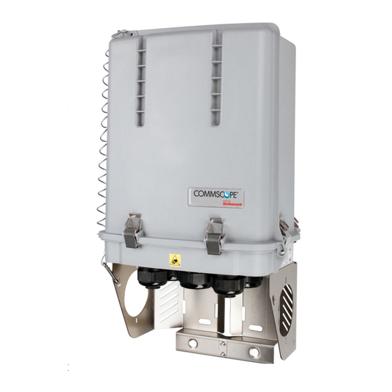
Summary of Contents for Raycap RCMDC-6627-PF-48
- Page 1 RCMDC-6627-PF-48 INSTALL INSTRUCTIONS Installation Instructions: RCMDC-6627-PF-48 www.raycap.com...
-
Page 3: Table Of Contents
Alarm Wiring 12.1 Installing Hybrid Cable-Fiber (In) 13.1 Installing Hybrid Cable-Fiber (Out) 14.1 Installation Complete. Closing and Securing Unit. (Optional) Addendum: High Power Wire Bridge Kit for Model RCMDC-6627-PF-48 ©Raycap • All rights reserved 320-1204 Rev.E www.raycap.com Page 1 of 38... -
Page 4: Copyright
ATTENTION – Installation of the hybrid cable requires an approved hanger to be used no more than 3 feet from the entrance of the Raycap unit. Refer to cable manufacturer’s instructions for proper hardware. CAUTION – Do not bend fiber-optic cables beyond their minimum bend radius. Bending the cables beyond their minimum bend radius can damage the cables and cause problems that are difficult to diagnose. -
Page 5: Introduction
• Mounting hardware accessories (bolts, washers and nuts) Prerequisites This document describes how to install the RCMDC-6627-PF-48 on-site and how to mount, and connect it to external interfaces. Installers of Raycap’s RRH surge protective and fiber/power management solutions must be industry professionals who have attended training on the proper installation of the equipment by Raycap and/or the mobile operator. -
Page 6: General Install Information
INSTALL INSTRUCTIONS General Install Information Whenever installing a RCMDC-6627-PF-48 at the top and connecting it at the base to a RCMDC-4520-RM-48x, RCMDC-2260-RM-48, or a RCMDC-3315-PF-48, the (4520), (2260) or (3315) should include a retrofitted alarm board to communicate properly to the newly installed (6627). -
Page 7: Procedure
2 glands fit 2 each #6 12 cond DC 190-0905 2x 10.5mm 2x12 Fiber 1 gland fit 2 x 12 fiber trunk 190-0912 2x 9.5mm 2 ETH 1 gland fits 2 ethernet cable ©Raycap • All rights reserved 320-1204 Rev.E www.raycap.com Page 5 of 38... -
Page 8: Pre-Wiring Preparation Procedure
Ensure the lanyard from enclosure lid to enclosure base is secure. Open up clamps on all sides of the enclosure cabinet by lifting the hinged clamp tabs. Remove enclosure lid. ©Raycap • All rights reserved 320-1204 Rev.E www.raycap.com Page 6 of 38... - Page 9 Board Alarm Connector Strikesorb Module Mode Select -48V Switch Connection Return Alarm Connection Connector Fiber Connectors Hybrid Trunk Ground Points Fiber Connection Fiber Fiber Panel Panel Management Label ©Raycap • All rights reserved 320-1204 Rev.E www.raycap.com Page 7 of 38...
-
Page 10: Cable Installation Instructions
Insert needs to be 1" behind heat shrink tube. Carefully feed fiber and power conductors into the OVP box and tighten the compression nut. Torque: approximately 44 in-lbs ©Raycap • All rights reserved 320-1204 Rev.E www.raycap.com Page 8 of 38... -
Page 11: Installing Hybrid Cable-Power (In)
6th: OVP #6 and OVP #12 Torque: 40 in-lbs (10-6 AWG) Circuit Identification Color -48V 1, 7 Blue 2, 8 Violet 3, 9 Green 4, 10 Brown 5, 11 Yellow 6, 12 White ©Raycap • All rights reserved 320-1204 Rev.E www.raycap.com Page 9 of 38... -
Page 12: Installing Hybrid Jumper Cable-Power (Out)
5th: OVP #5 and OVP #11 6th: OVP #6 and OVP #12 Torque: 40 in-lbs (10-6 AWG) Jumpers 1-6 installed (Hybrid Trunk not shown for clarity) Jumpers 1-12 installed -48V Return ©Raycap • All rights reserved 320-1204 Rev.E www.raycap.com Page 10 of 38... -
Page 13: Installing Ground Cable
RCMDC-6627-PF-48 INSTALL INSTRUCTIONS Installing Ground Cable 10.1 There are two grounding placement options available. See below. Hybrid Trunk Ground Points Main Ground Optional Cable Grounds ©Raycap • All rights reserved 320-1204 Rev.E www.raycap.com Page 11 of 38... -
Page 14: Alarm Wiring
RCMDC-6627-PF-48 INSTALL INSTRUCTIONS 11.0 Alarm connections for RCMDC-6627-PF-48 Installing Alarm Wiring for RCMDC-6627-PF-48 Tower Top Configuration 11.1 Alarm Output to BTS (not used in Tower Top Configuration) Rotary Switch · ) & 1 are identical in functionality, therefore either may be selected for tower top mode... - Page 15 Tower Top Unit (receiving (receiving (both dots blink daisy chain data) tower top data) indicating transmission) Circuit status messages: Low Voltage Reverse Polarity Short Circuit (less than 35V) ©Raycap • All rights reserved 320-1204 Rev.E www.raycap.com Page 13 of 38...
- Page 16 Base mode operation. Place rotary switch to position “2” which corresponds to base mode address “0” If in daisy chain configuration, place selector switch to the next base mode address ©Raycap • All rights reserved 320-1204 Rev.E www.raycap.com Page 14 of 38...
- Page 17 Address Select Switch Place rotary switch to position “0” which corresponds to base address “0” If in daisy chain configuration, place selector switch to the next base address ©Raycap • All rights reserved 320-1204 Rev.E www.raycap.com Page 15 of 38...
- Page 18 RCMDC-6627-PF-48 INSTALL INSTRUCTIONS 11.6 Standard Base/Tower Configuration. (1) RCMDC-6627-PF-48 unit at the tower top and (1) RCMDC-4520-RM-48x unit at the base. Note: Selector switch set to “•” or ”1” for Tower Top mode Alarm Outputs to BTS Note: Selector switch set to “0”...
-
Page 19: Install Instructions Rcmdc-6627-Pf
RCMDC-6627-PF-48 INSTALL INSTRUCTIONS 11.7 Standard Base/Tower Configuration. (1) RCMDC-6627-PF-48 unit at the tower top and (1) RCMDC-6627-PF-48 unit at the base. Tower Top Unit Note: Selector switch set to “•” or ”1” for Tower Top mode Tower-Base communication Base Unit Alarm Outputs... - Page 20 RCMDC-6627-PF-48 INSTALL INSTRUCTIONS 11.8 Daisy Chain Configuration. (2) RCMDC-6627-PF-48 units at the tower top and (2) RCMDC-6627-PF-48 units at the base. Tower Top Unit #1 Note: Selector switch set to “•” or ”1” for Tower Top mode Tower-Base communication Base “0” Note: Selector switch set to “2”...
- Page 21 Base “1” Alarm Outputs to BTS Note: Selector switch set to “3” for Base mode address “1” Daisy Chain Input Daisy Chain Output to next Base unit ©Raycap • All rights reserved 320-1204 Rev.E www.raycap.com Page 19 of 38...
- Page 22 This wiring scenario will be almost identical to (2) base-located RCMDC-3315-PF-48 units with Retrofit Kits. Tower Note: Selector switch set to “•” or ”1” for Tower Top mode ©Raycap • All rights reserved 320-1204 Rev.E www.raycap.com Page 20 of 38...
- Page 23 “0” Base “1” Daisy Chain Output to next Base unit Daisy Chain Input Note: Selector switch set to “3” for Base mode Alarm Outputs address “1” to BTS ©Raycap • All rights reserved 320-1204 Rev.E www.raycap.com Page 21 of 38...
- Page 24 RCMDC-6627-PF-48 INSTALL INSTRUCTIONS 11.10 RCMDC-6627-PF-48 at the Tower Top connected to (2) RCMDC-2260-RM-48 racks, one with a Retrofit Kit and one without at the base. 6627 Dome Note: Selector switch set to “•” or ”1” for Tower Top mode ©Raycap • All rights reserved 320-1204 Rev.E www.raycap.com Page 22 of 38...
- Page 25 RCMDC-6627-PF-48 INSTALL INSTRUCTIONS 2260 Rack (Original Alarm Board) 2260 Rack (Retrofit Alarm Board) Alarm Note: Outputs Selector switch set to to BTS “2” for Base mode address “0” ©Raycap • All rights reserved 320-1204 Rev.E www.raycap.com Page 23 of 38...
-
Page 26: Installing Hybrid Cable-Fiber (In)
Connect the cables into the fiber connection panel starting with the row closest to the back plate, and feed through the cable guides. 12.4 Connect fiber according to the Verizon Wireless established guide. ©Raycap • All rights reserved 320-1204 Rev.E www.raycap.com Page 24 of 38... -
Page 27: Installing Hybrid Cable-Fiber (Out)
13.4 Connect fiber according to the Verizon Wireless established guide. ©Raycap • All rights reserved 320-1204 Rev.E www.raycap.com Page 25 of 38... - Page 28 RCMDC-6627-PF-48 INSTALL INSTRUCTIONS Installation Complete. Installed cable routing examples: ©Raycap • All rights reserved 320-1204 Rev.E www.raycap.com Page 26 of 38...
-
Page 29: Installation Complete. Closing And Securing Unit
Slide enclosure lid into place. Red must be completely covered for proper lid alignment. 14.2 If installation requires padlocks, (not provided) secure “bottom right” enclosure. 14.3 As pictured, Lid IS properly aligned. ©Raycap • All rights reserved 320-1204 Rev.E www.raycap.com Page 27 of 38... - Page 30 6627 “4520” = 12 OVP Rack | “2260” = 6 OVP Rack | “6627” = 12 OVP Dome | “3315” = 6 OVP Dome “with Retrofit” = Retrofit Alarm Board installed ©Raycap • All rights reserved 320-1204 Rev.E www.raycap.com Page 28 of 38...
- Page 31 RCMDC-6627-PF-48 INSTALL INSTRUCTIONS Addendum High Power Wire Bridge Kit (Optional) For Model RCMDC-6627-PF-48 ©Raycap • All rights reserved 320-1204 Rev.E www.raycap.com Page 29 of 38...
- Page 32 This documentation is intended for the use of Raycap customers only for the purposes of the agreement under which the document is submitted, and no part may be used, reproduced, modified or transmitted in any form or means without the prior written permission of Raycap.
- Page 33 Install -48V jumper wire between first -48V and second OVP with kep nut using 7/16" socket. Install RTN jumper wire between first and second OVP with kep nut using 7/16" socket. ©Raycap • All rights reserved 320-1204 Rev.E www.raycap.com Page 31 of 38...
- Page 34 Install 4 insulator caps over custom installed lugs. Insulator Caps A.2.5 Remaining 4 lugs ready for high power radio installation. A.2.6 Installation complete connecting 2 circuits for high power radios. ©Raycap • All rights reserved 320-1204 Rev.E www.raycap.com Page 32 of 38...
- Page 35 RCMDC-6627-PF-48 INSTALL INSTRUCTIONS Vertical Installation Completed A.2.7 Completed Wiring example. See below. ©Raycap • All rights reserved 320-1204 Rev.E www.raycap.com Page 33 of 38...
- Page 36 Install -48V jumper wire between first -48V and second OVP with kep nut using 7/16" socket. Install RTN jumper wire between first and second OVP with kep nut using 7/16" socket. ©Raycap • All rights reserved 320-1204 Rev.E www.raycap.com Page 34 of 38...
- Page 37 Install 4 insulator caps over custom installed lugs. Insulator Caps A.3.5 Remaining 4 lugs ready for high power radio installation. A.3.6 Installation complete connecting 2 circuits for high power radios. ©Raycap • All rights reserved 320-1204 Rev.E www.raycap.com Page 35 of 38...
- Page 38 RCMDC-6627-PF-48 INSTALL INSTRUCTIONS Horizontal Installation Completed A.3.7 Completed Wiring example. See below. ©Raycap • All rights reserved 320-1204 Rev.E www.raycap.com Page 36 of 38...
- Page 40 RCMDC-6627-PF-48 INSTALL INSTRUCTIONS ©Raycap • All rights reserved 320-1204 Rev.E www.raycap.com Page 38 of 38...
Need help?
Do you have a question about the RCMDC-6627-PF-48 and is the answer not in the manual?
Questions and answers
Can the alarm wires on the Top Side 12 OVP be wired to the Def1 ports? The base 12 OVP is wired to the Def2 ports
The alarm wiring for the RCMDC-6627-PF-48 in the Tower Top Configuration includes Tower Communication (D1) and Tower Communication (D2) ports, both used for RS485 communication. There is no mention of "Def1" ports in the provided information. Therefore, it cannot be determined if alarm wires can be wired to the Def1 ports.
This answer is automatically generated
Sorry that should have said Ref1 top side ref2 base
@Mr. Anderson Sorry that should have said Ref1 top side ref2 base