Harman Kardon AVR 245 Owner's Manual
Harman kardon avr 245: owners guide
Hide thumbs
Also See for AVR 245:
- Service manual (229 pages) ,
- Owner's manual (56 pages) ,
- Worksheet (3 pages)
Table of Contents
Advertisement
Advertisement
Table of Contents

Related Manuals for Harman Kardon AVR 245


Summary of Contents for Harman Kardon AVR 245
- Page 1 ® Designed to Entertain. ™ AVR 245 AUDIO/VIDEO RECEIVER OWNER’S MANUAL...
-
Page 2: Table Of Contents
Step Six – Plug in AC Power Step Seven – Insert Batteries in Remote Step Eight – Program Sources Into the Remote Step Nine – Turn On the AVR 245 INITIAL SETUP Using the On-Screen Menu System Configure the AVR 245 Using EzSet+... -
Page 3: Safety Information
CAUTION RISK OF ELECTRIC SHOCK DO NOT OPEN 1. Read Instructions. All the safety and operating instruc- tions should be read before the product is operated. 2. Retain Instructions. The safety and operating instruc- tions should be retained for future reference. 3. -
Page 4: Important Safety Information
• Do not obstruct the ventilation slots on the top of the unit, or place objects directly over them. • Due to the weight of the AVR 245 and the heat generated by the amplifiers, there is the remote possibility that the rubber padding on the bottom of the unit’s feet may leave marks on certain wood or veneer materials. -
Page 5: Introduction
Please register your AVR 245 on our Web site at www.harmankardon.com. Note: You’ll need the product’s serial number. At the same time, you can choose to be notified about our new products and/or special promotions. Thank you for choosing Harman Kardon... -
Page 6: Audio Inputs
• Remote infrared (IR) input and output • Multiroom IR input Supplied Accessories The following accessory items are supplied with the AVR 245. If any of these items are missing, please contact Harman Kardon customer service at www.harmankardon.com. • System remote control •... -
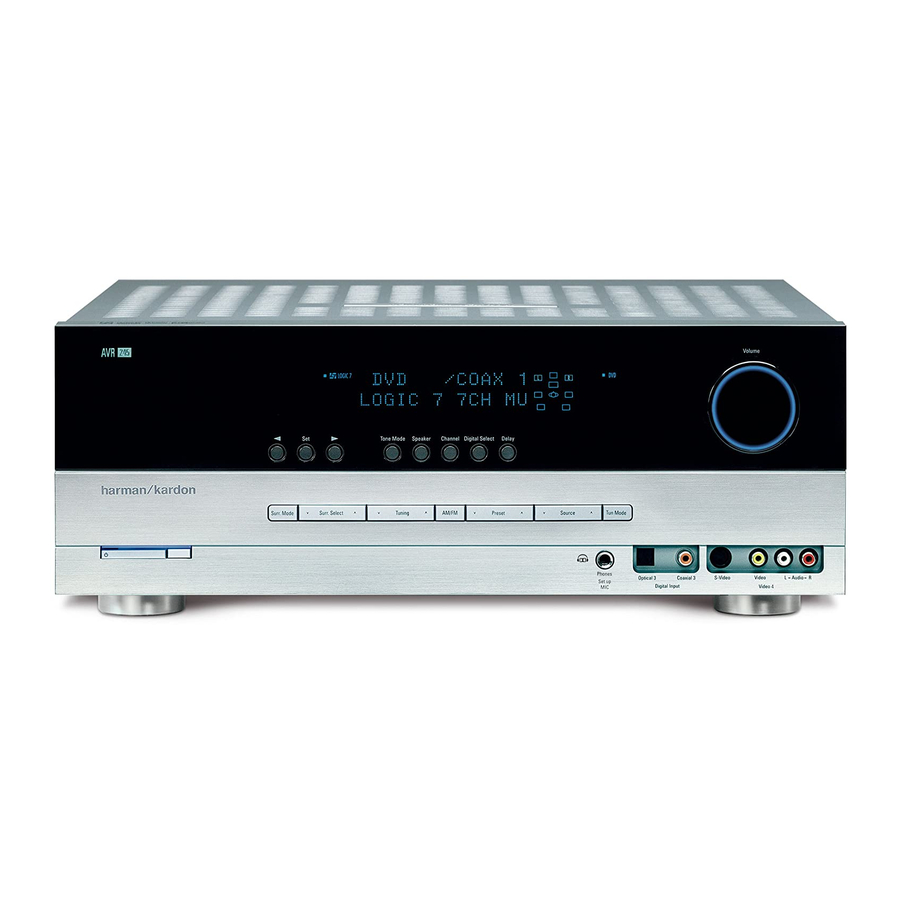
Page 7: Front-Panel Controls
Power Indicator: This LED has three possible modes. When main power is turned off, the LED is dark and the receiver won’t respond to any button presses. When main power is turned on, but before the Standby/On Switch is used, the LED turns amber to indicate that the receiver is in Standby mode and ready to be turned on. -
Page 9: Rear-Panel Connections
AVR’s coaxial or optical digital audio inputs to benefit from the AVR 245’s multichannel audio processing. The AVR 245 will not convert other types of video to HDMI, and you will not be able to view the on-screen displays using the HDMI connection. - Page 10 AVR 245’s on-screen displays. RS-232 Serial Port: This specialized connector may be used with your personal computer in case Harman Kardon offers a software upgrade for the receiver at some time in the future. RS-232 Mode: Leave this switch popped out in the Operate position unless the AVR 245 is being upgraded.
-
Page 12: Remote Control Functions
REMOTE CONTROL FUNCTIONS The AVR 245 remote is capable of controlling 11 devices, including the AVR itself and an iPod docked in the optional The Bridge accessory. During the installation process, you may program the codes for each of your source components into the remote. Each time you wish to use the codes for any component, you will need to first press the Selector button for that component. - Page 13 IR Transmitter Lens Power On Program Indicator AVR Selector AM/FM XM Radio Test Tone Sleep DSP Surround On-Screen Display Channel Level Digital Input Tuning Mode Direct Station Entry Tuning Tone Mode Night Mode Track Skip Transport Controls Mute Power Off Input Selectors 6-Channel Input Selector TV/Video...
-
Page 14: Night Mode
Transport Controls: but are used to control many source components. By default, when the remote is operating the receiver, these buttons will control a DVD player. Press these buttons to tune a radio station or XM Radio chan- Press this button before using the Numeric Keys to directly... -
Page 15: Introduction To Home Theater
Surround sound immerses you in the musical or film presentation for increased realism. The AVR 245 may have up to seven speakers connected directly to it (plus a subwoofer). Each main speaker is powered by its own amplifier channel inside the receiver. When more than two speakers are used, it is called a multichannel system. -
Page 16: Connections
Figure 3 – Subwoofer Connecting Source Devices to the AVR The AVR 245 is designed to process audio and video input signals, playing back the audio and displaying the video on a television or moni- tor connected to the AVR. These signals originate in what are known as “source devices,”... -
Page 17: Audio Connections
The AVR 245 is only capable of processing one PCM source at a time. -
Page 18: Digital Video Connections
In addition, receivers and processors such as the AVR 245 may handle the incoming signal in several different ways, depending on their capabil- ity as well. The AVR 245 is only capable of switching the HDMI data. That is, the incoming audio and video data will be passed directly to your HDMI-capable video display, without the AVR 245 processing any of the data. -
Page 19: Speaker Placement
Placement of the surround speakers depends on the number of speakers in your system. If you’re using only two speakers with the AVR 245, place them in the front left and right positions, and skip to the Installation section. However, Harman Kardon recommends using the AVR 245 in a 5.1- or 7.1-channel configuration for optimal... - Page 20 Place the subwoofer in that spot. NOTE: Your receiver will sound its best when the same model loudspeaker is used for all positions (other than the subwoofer).
-
Page 21: Installation
Surround Back Left speaker outputs. Step Two – Connect the Subwoofer Connect the Subwoofer Output on the AVR 245 to the line-level input on your subwoofer. See Figure 18. Consult the manufacturer’s guide for the subwoofer for additional information. - Page 22 Table 2 – Recommended Source Component Connections We recommend connecting your various sources using the connections shown in Table 2 (below) in order to simplify programming your receiver and remote control. However, you may connect any device to any source input.
- Page 23 NOTE: The AVR 245 is equipped with a total of six digital audio inputs, four on the rear panel (Coaxial 1 and 2, Optical 1 and 2) and two on the front panel (Coaxial 3 and Optical 3). However, there are a total of nine sources that may be connected to devices that have digital audio outputs.
- Page 24 Blu-ray Disc player or HDTV tuner. The HDMI 1 source is not used with any of the 2-channel analog audio or video inputs on the AVR 245. Since the AVR 245 is not capable of processing either the audio or video signal transmitted via the HDMI connection, you will need to connect the source’s coaxial digital audio output to the Coaxial 2 digital audio input...
-
Page 25: Step Five - Connect Video Display
AVR 245. See Figure 34. Make sure this device draws no more than 50 watts. The device should have its mechanical or master power switch turned on, and it will power on any time the AVR 245 is turned on. -
Page 26: Step Eight - Program Sources Into The Remote
Figure 35 – Remote Battery Compartment When using the remote, remember to point the lens toward the front panel of the AVR 245. Make sure no objects, such as furniture, are blocking the remote’s path to the receiver. Bright lights, fluorescent lights and plasma video displays may interfere with the remote’s functioning. -
Page 27: Step Nine - Turn On The Avr 245
Remote Control Code Figure 37 – Power Switches 2. There are several ways in which the AVR 245 may be turned on from Standby mode. a) Press the Standby/On Switch on the front panel. See Figure 37. b) Press the Source Select Button on the front panel. See figure 38. - Page 28 VID2, VID3 or VID4), the remote will switch modes so that it will only transmit the codes programmed to operate that device. In order to control the receiver, you will need to press the AVR button to return the remote to AVR mode.
-
Page 29: Initial Setup
Before you begin enjoying your new receiver, a few adjustments should be made to configure the AVR 245 to match your actual system. Make sure that you have connected a video display to either the S-video or composite video monitor output on the receiver. When you turn on your display and the AVR, you should see a blue screen. - Page 30 Figure 42. Figure 42 – Plug EzSet+ microphone into receiver. Step Three – Make sure that the AVR 245 and the video display are turned on. Press the OSD Button to display the Master Menu. See Figures 40 and 41. Use the Buttons to move the cursor to the ⁄...
-
Page 31: What Ezset+ Does
What EzSet+ Does EzSet+ will send test signals to the various speakers and perform the measurements described in this section, adjusting the AVR 245’s set- tings to match EzSet+’s internal references. Set Master Volume Level: EzSet+ sends test tones to the front speakers and adjusts the system’s volume level to enable it to take the... -
Page 32: Configure Sources
INITIAL SETUP Figure 51 – EzSet+ – Speaker Delay NOTE: The AVR 245 is also capable of setting a different type of delay, called A/V Sync Delay. A/V Sync Delay is used to com- pensate for lip sync problems that may occur when a video dis- play device or set-top box causes delays while digital video sig- nals are processed. - Page 33 AUTO POLL: The Auto Poll feature is used when both an analog audio and digital audio connection have been made for one source device. If for some reason no digital signal is available, the AVR 245 will switch to the analog inputs for the source. This situation can occur with some cable or satellite television broadcasts, where some channels are broad- cast with digital audio and others with analog audio.
- Page 34 NOTE: In order to access the DMP SETTING menu, you need to press the AVR Selector on the remote so that it operates the AVR 245. You may then press the OSD Button and use the Navigation and Set Buttons, as usual, with the on-screen menu system.
-
Page 35: Operation
See Figure 57. Figure 57 – Power Switches There are several ways in which the AVR 245 may be turned on: a) Press the Standby/On Switch on the front panel. See Figure 57. -
Page 36: Mute Function
For direct access to any source, press its Input Selector on the remote (see Figure 59). Since the AVR 245 allows for more source input devices than the remote has buttons for, some sources are required... -
Page 37: Audio Input Selection
Each additional press toggles between the two sources. The AVR 245 will switch to the audio and video inputs assigned to the source. If you set the BASS MGR setting in the Speaker X-over menu... -
Page 38: Using The Tuner
(see Advanced Functions section). Consult the owner’s guide for your multichannel player for more information. Using the Tuner The AVR 245’s built-in tuner may be selected in one of three ways (see Figure 68): 1. Press the Source Selector Button on the front panel repeatedly until the tuner is selected. -
Page 39: Xm Radio Operation
XM Radio is a satellite-delivered service that offers hundreds of program channels, as well as local traffic and weather information for select cities. The AVR 245 is “XM Ready,” which means that it is able to receive the XM service when an optional XM antenna module is connected and the service activated. -
Page 40: Recording
The Bridge is an optional dock that may be used with a compatible iPod (not included). When The Bridge is connected to its proprietary input on the AVR 245 and the iPod is docked, you may play the audio materials on your iPod through your high-quality audio system, operate the iPod using the AVR remote or the AVR’s front-panel controls, view navigation... -
Page 41: Selecting A Surround Mode
Surround mode selection can be as simple or sophisticated as your individual system and tastes. Feel free to experiment with the many available surround modes on the AVR 245, and you may find a few that become your favorites for certain sources or program types. Although... -
Page 42: Advanced Functions
ADVANCED FUNCTIONS Much of the AVR 245’s performance is handled automatically, with little intervention required on your part. However, the AVR 245 is a sophisti- cated component, and is capable of being customized to suit your par- ticular system and your tastes. In this section we describe some of the more advanced adjustments available on the AVR 245. -
Page 43: Surround Modes
There is no harm in experimenting with all of the modes available with any given source material. Table 6 offers a brief description of each mode the AVR 245 is capable of using, and also indicates the types of incoming signals or digital bitstreams the mode may be used with. -
Page 44: Dolby Surround Settings
Default Modes During initial use or after a processor reset, the AVR 245 will default to the Logic 7 Music mode for all analog and PCM audio inputs. Subse- quently, when a source input is selected and an analog or PCM signal is received, the AVR will switch to the last surround mode used for that source input/incoming signal combination. - Page 45 Dolby Pro Logic IIx modes may be selected not only with Dolby Digital bit- streams, but thanks to the AVR 245’s post-processor, they may also be used with some DTS bitstreams to add a surround back channel to 5.1 modes.
- Page 46 ADVANCED FUNCTIONS Surround Mode Description Dolby Pro Logic IIx This mode is similar to Dolby Pro Logic II Music, including the availability Music of center width, dimension and panorama adjustments. Dolby Pro Logic IIx Music adds a surround back channel. In addition, it may be selected even when some types of DTS signals are present.
- Page 47 Cinema encoding, Logic 7 Cinema mode increases center channel intelligibility. Logic 7 The AVR 245 is programmed at the factory to default to this mode for Music 2-channel signals. Logic 7 Music mode is well suited to conventional 2-channel music recordings.
-
Page 48: Manual Setup
ADVANCED FUNCTIONS Manual Setup The AVR 245 is flexibly designed to be used with almost any loud- speakers available. The flexibility arises from the AVR 245’s capability to be configured to match the characteristics of your particular speakers, and to compensate for the acoustic characteristics of your room. -
Page 49: Speaker Size Menu
SURR BACK: Use the ‹/› Buttons to select the SMALL, LARGE or NONE setting for the surround back speakers. The AVR 245 is one of the few receivers in its class to include multi- room capability. With assignable surround back amplifier channels, set- ting up a multiroom system is more convenient than ever, no longer requiring an external amplifier to power the remote speakers. -
Page 50: Speaker Crossover Menu
ADVANCED FUNCTIONS NOTE: If you are using a Harman Kardon HKTS speaker sys- tem, select the SMALL setting for the LEFT/RIGHT, CENTER and SURROUND lines, and the subwoofer will automatically be set to SUB. BASS MGR: This advanced setting is used if you wish to configure your speakers differently for different sources. -
Page 51: Step Four - Setting Channel Output Levels Manually
If you ran EzSet+, then the output levels were set automatically at that time. However, if you prefer to make these adjustments manually, the AVR 245’s Channel Adjust menu allows you to do so, either using the system’s test tone or while playing source material. -
Page 52: Multiroom Operation
If you are using an external source to set your output levels, simply navi- gate to each channel and use the desired. If you would like to set your levels using the AVR 245’s internal test tone, you will need to adjust the TEST TONE SEQ and TEST TONE lines as follows. -
Page 53: Installing A Multiroom System
Tuning Mode Button to select monaural operation for FM radio stations. If you wish to use the AVR 245 with more than one remote room, you will need to purchase a multichannel external amplifier that enables you to connect several pairs of loudspeakers. -
Page 54: Dim Function
Advanced Remote Control Functions The AVR 245 remote control not only operates the AVR 245, but it also serves as a universal remote that may be programmed to operate many other home theater components, as described in the Installation section. -
Page 55: Macros
To program punch-through control while operating any device: 1. Press and hold the Input Selector (or AVR selector) for the main device the remote will be operating until the LED flashes and the remote enters program mode. 2. Select the type of punch-through programming. a) To program volume control punch-through, press the Volume Up Button. -
Page 56: Remote Ir Inputs And Output
Remote IR Output to facilitate use of your system with a remote control in a variety of situations. When the AVR 245 is placed in such a way that aiming the remote at the front-panel IR sensor is difficult, such as inside a cabinet or facing away from the listener, you may connect an external IR receiver, such as the optional Harman Kardon HE 1000, to the Remote IR Input jack. -
Page 57: Troubleshooting Guide
• XM antenna is not located in such In addition to the items shown above, additional information on troubleshooting possible problems with your AVR 245, or installation-related issues, may be found in the list of "Frequently Asked Questions" which is located in the Product Support section of our Web site at www.harmankardon.com. -
Page 58: Technical Specifications
IF Rejection 90dB Please register your AVR 245 on our Web site at www.harmankardon.com. Note: You’ll need the product’s serial number. At the same time, you can choose to be notified about our new products and/or special promotions. AM Tuner Section Frequency Range 520–1720kHz... -
Page 59: Appendix
Appendix – Default settings, worksheets, remote product codes Table A1 – Source Input Setting Defaults Source HDMI 1 HDMI 2 Title Component Comp V 1 Convert*** Convert*** Comp V 2 Comp V 3 Convert*** Convert*** Convert*** Video Input Audio Input Coax 1 Coax 2 Optical 2 Auto Poll... - Page 60 APPENDIX Table A4 – Source Input Settings Source HDMI 1 HDMI 2 Video 1 Video 2 Video 3 Video 4 The Bridge/DMP Title Video Input Component Video Input Audio Input Auto Poll Surround Mode Table A5 – Speaker/Channel Settings Source HDMI 1 HDMI 2 Video 1 Video 2 Video 3 Video 4 The Bridge/DMP Bass Manager: Global/Independent...
- Page 61 Table A6 – Remote Control Codes Source Input Product Type (circle one or fill in) Video 1 VCR, PVR Video 2 Cable, Satellite Video 3 Video 4 CD, CDR Tape Cassette HDMI 1 HDMI 2 Table A7 – System Settings Feature Default Setting VFD Fade Time Out...
- Page 62 APPENDIX Refer to the numbered buttons in Figure 88 when using the Function List. Figure 88 – Remote Control Function List Reference 52 53 65 66...
- Page 63 Table A8 – Remote Control Function List Button Name AVR Function CD/CD-R Power On Power On Power On Power On Power Off Power Off Power Off Power Off Mute Mute Mute Mute AVR Sel e ct AVR Sel e ct AVR Sel e ct DVD/CD DVD I n put Sel e ct...
- Page 64 APPENDIX Button Name AVR Function CD/CD-R Memory Memory Audi o or Pl a yl i s t Ti m e Tuning Up Tuning Up Next Chapter Track Direct Direct Direct Tuner Entry Angle Random Play Clear Clear Clear Clear Preset Up Preset Tune Up Sl o w Forward Tuning Down Tuning Down...
- Page 65 CAPEHART CENTURION CENTRONIC CITIZEN CLASSIC CONCERTO CONTEC CORANDO CORONADO CRAIG CROWN CURTIS MATHES DAEWOO DAYTRON DIGI LINK DYNASTY DYNATECH ELECTROHOME EMERSON FUNAI FUTURETECH GOLDSTAR/LG GRUNDIG HALL MARK HARMAN KARDON HITACHI INFINITY INKEL JC PENNEY JENSEN KAWASHO KENWOOD LLOYTRON LODGENET APPENDIX...
- Page 66 APPENDIX Manufacturer/Brand Setup Code Number LOGIK LUXMAN MAGNAVOX MARANTZ MATSUI MEMOREX METZ MINERVA MITSUBISHI NATIONAL NIKEI ONKING ONWA OPTONICA ORION PANASONIC PHILCO PHILIPS PIONEER PORTLAND PROSCAN PROTON QUASAR RADIO SHACK REALISTIC RUNCO SAMPO SAMSUNG SANYO SCOTT SEARS SHARP SIEMENS SIGNATURE SONY SOUNDESIGN SPECTRICON...
- Page 67 Manufacturer/Brand Setup Code Number TEKNIKA TELERENT TERA THOMSON TOSHIBA TOTEVISION VIDEO CONCEPTS VIDTECH WARDS YAMAHA YORK YUPITERU ZENITH ZONDA APPENDIX...
- Page 68 018 048 DYNATECH EMERSON 013 040 042 110 112 FISHER FUNAI 076 095 124 GO VIDEO GOLDSTAR/LG 018 107 HARMAN KARDON 002 003 018 049 HITACHI 040 048 JC PENNEY 018 045 JENSEN 018 048 111 132 KENWOOD 020 048...
- Page 69 Manufacturer/Brand Setup Code Number REALISTIC 017 020 040 045 159 SALORA SAMSUNG 045 051 095 105 109 SANSUI 048 116 147 SANYO 017 020 SCOTT 110 112 SEARS 017 020 SHARP 129 156 SONY 080 129 SOUNDESIGN SYLVANIA SYMPHONIC TANDY 017 040 TASHICO TATUNG...
- Page 70 AKAI AUDIO TECHNICA AUDIOACCESS AUDIOFILE CALIFORNIA AUDIO CAPETRONIC CARRERA CARVER CASIO CLARINETTE DENON EMERSON FISHER FRABA FUNAI GENEXXA GOLDSTAR/LG HAITAI HARMAN KARDON HITACHI INKEL JC PENNEY JENSEN KENWOOD LOTTE LUXMAN MAGNAVOX MARANTZ MCINTOSH MITSUMI MODULAIRE NAKAMICHI NIKKO ONKYO OPTIMUS PANASONIC...
- Page 71 Table A12 – Remote Control Product Codes – DVD Manufacturer/Brand Setup Code Number APEX DIGITAL DENON 019 051 003 004 GOLDSTAR/LG 005 055 064 066 HARMAN KARDON 001 002 068 MAGNAVOX MARANTZ MITSUBISHI ONKYO 009 048 PANASONIC 024 030 044...
- Page 72 APPENDIX Table A13 – Remote Control Product Codes – SAT Manufacturer/Brand Setup Code Number ALPHASTAR ALPHASTAR DBS ALPHASTAR DSR BIRDVIEW CHANNEL MASTER 320 321 CHAPARRAL 315 316 CITOH DRAKE 313 317 DX ANTENNA 331 352 ECHOSTAR 395 397 ELECTRO HOME FUJITSU 324 329 GENERAL INSTRUMENT...
- Page 73 Table A14 – Remote Control Product Codes – TAPE Manufacturer/Brand Setup Code Number HARMAN KARDON Table A15 – Remote Control Product Codes – CBL Manufacturer/Brand Setup Code Number 001 011 ALLEGRO AMERICAST ARCHER BELCOR CABLE STAR 033 113 CITIZEN COLOUR VOICE...
- Page 74 UNITED CABLE UNIVERSAL 033 034 039 042 113 VIDEOWAY 124 211 VIEWSTAR 019 025 086 089 190 ZENITH 065 125 211 219 ZENTEK Table A16 – Remote Control Product Codes – THE BRIDGE/DMP Manufacturer/Brand Setup Code Number HARMAN KARDON TEN TECHNOLOGIES...
- Page 75 NOTES...
- Page 76 ® 250 Crossways Park Drive, Woodbury, New York 11797 www.harmankardon.com © 2006 Harman International Industries, Incorporated. All rights reserved. Part No. CQX1A1133Z...
Need help?
Do you have a question about the AVR 245 and is the answer not in the manual?
Questions and answers