Harman Kardon AVR247 Service Manual
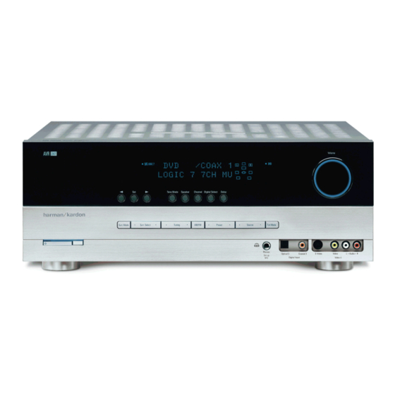
5 x 50w 7.1 channel a/v receiver
Hide thumbs
Also See for AVR247:
- Service manual (206 pages) ,
- Owner's manual (76 pages) ,
- Worksheet (3 pages)
Advertisement
harman/kardon
harman/kardon
AVR247/230
5 x 50W 7.1 CHANNEL A/V RECEIVER
ESD WARNING..................................2
BASIC SPECIFICATIONS........................3
TROUBLESHOOTING GUIDE.................4
PROCESSOR RESET..............................4
PACKAGE LIST AND PARTS..................5
DISASSEMBLY.........................................6
UNIT EXPLODED VIEW AND PARTS...11
Released EU2008
CONTENTS
ELECTRICAL PARTS LIST...............12
SEMICONDUCTOR PINOUTS...........54
PCB DRAWINGS..........................110
BLOCK DIAGRAM.............................119
WIRING DIAGRAM........................120
AMP BIAS ADJUSTMENT................121
SCHEMATIC DIAGRAMS................122
harman/kardon, Inc.
250 Crossways Park Dr.
Woodbury, New York, 11797
AVR247/230 Service Manual
Service Manual
Rev 0, 05/2008
Page 1 of 131
Advertisement

Related Manuals for Harman Kardon AVR247


Summary of Contents for Harman Kardon AVR247
-
Page 1: Service Manual
AVR247/230 Service Manual harman/kardon Service Manual AVR247/230 5 x 50W 7.1 CHANNEL A/V RECEIVER CONTENTS ESD WARNING………………………..…..2 ELECTRICAL PARTS LIST…….…..…12 BASIC SPECIFICATIONS......3 SEMICONDUCTOR PINOUTS…..….54 TROUBLESHOOTING GUIDE....4 PCB DRAWINGS…………………..…110 PROCESSOR RESET......4 BLOCK DIAGRAM......119 PACKAGE LIST AND PARTS…....5 WIRING DIAGRAM……………..….…120 DISASSEMBLY.........6 AMP BIAS ADJUSTMENT...…...…..121... - Page 2 AVR247/230 Service Manual Some semiconductor (solid state) devices can be damaged easily by static electricity. Such components commonly are called Electrostatically Sensitive (ES) Devices. Examples of typical ES devices are integrated circuits and some field effect transistors and semiconductor "chip" components.
-
Page 3: Technical Specifications
AVR247/230 Service Manual Technical Specifications Audio Section FM Tuner Section Stereo Mode Frequency Range 87.5–108MHz Continuous Average Power (FTC) Usable Sensitivity IHF 1.3 µV/13.2dBf Signal-to-Noise Ratio Mono/Stereo: 70/68dB (DIN) 65 Watts per channel, 20Hz–20kHz, Distortion Mono/Stereo: 0.2/0.3% @ < 0.07% THD, both channels driven into 8 ohms... -
Page 4: Troubleshooting Guide
Power switch 2 is red due to possible short and speaker ends • Amplifier is in protection mode • Contact your local Harman Kardon service depot due to internal problems No sound from surround or • Incorrect surround mode •... - Page 5 AVR247/230 Service Manual AVR247/230 1. Instruction manual ass'y - Accessories 2. Package Drawing MICROPHONE ASS'Y ACCESSORY-1 FM 1 POLE ANT POLY BAG AM LOOP ANTENNA ASS'Y BATTERY ASS'Y SNOW PAD (L) SNOW PAD (R) REMOCON ASS'Y IMAGE BROCHURES STAPLE...
- Page 6 AVR247/230 Service Manual DISASSEMBLY AVR247/230 1. Removing the Top Cabinet 3. Removing the Rear Panel Remove the Screws Remove the Screws 23 24 19 20 29 30 4. Removing the Main PCB Remove the Screws 2. Removing the Front Panel...
-
Page 7: Disassembly
AVR247/230 Service Manual DISASSEMBLY PROCEDURES (AVR247) <1> TOP-CABINET(21) REMOVAL 1. Remove 13 screws(S1,S7) and then remove the Top-cabinet. <2> FRONT PANEL ASS’Y REMOVAL 1. Remove the Top-cabinet, referring to the previous step<1>. 2. Disconnect the card cable between connector(CN72-17p) on the Fip PCB(37-1) and connector(CN72) on the Input PCB(39-1). - Page 8 AVR247/230 Service Manual 6. Disconnect the connector (CN89) on the Fip PCB(37-1) from lead wire(BN89-4P) on the Key PCB(37-2). 7. Remove 3 screws(S2) and then remove the Guide PCB(37-8) & the Fip PCB(37-1). <7>KEY PCB(37-2) REMOVAL 1. Remove the Top-cabinet, referring to the previous step<1>.
- Page 9 AVR247/230 Service Manual 8. Remove 2 screws(S13) and then remove the iPod PCB(39-2). <12>XM PCB(39-4) REMOVAL 1. Remove the Top-cabinet, referring to the previous step<1>. 2. Remove the Hudson PCB(42), referring to the previous step<9>. 3. Remove the Video PCB(41), referring to the previous step<10>...
- Page 10 AVR247/230 Service Manual from the lead wire(BN19-3P,BN20-4P) on the Main PCB(38-1). 4. Disconnect the lead wire(BN96-8P) on the Power PCB(40-4) from connector(CN96) on the Regulator PCB(B)(40-5). 5. Disconnect the lead wire(BN99-8P) on the Power PCB(40-4) from connector(CN99) on the Regulator PCB(A)(40-2).
-
Page 11: Exploded View
AVR247/230 Service Manual AVR247/230 EXPLODED VIEW 37-7 40-3 40-1 40-4 39-2 39-1 40-5 40-2 38-2 38-1 40-7 39-5 40-2 DESCRIPTION PARTS NO. Q,ty REMARK ORNAMENT,VOLUME CGU1A318Z CAP,VOLUME CGX1A338MBC63 HOLDER,VOLUME CMH1A214 INDICATOR,VOLUME CGL1A222 WINDOW ASS'Y CGUAVR247 WINDOW,FIP CGU1A399Y BADGE,MODEL CGB1A179Z... - Page 12 CPS1A676 PAD , COVER CQE1A220Z SHEET , FRONT COVER SHEET CQE1A180Z BOOKLET , IMFORMATIONS BOOKLET CQX1A1255Z MANUAL , INSTRUCTION AVR247/230 SHEET CQX1A1256Z MANUAL , SET UP AVR147/230 MANUAL CSA1A018Z FM 1 POLE ANT CSA1A027Z AM LOOP ANT HQE1A273Z HARMAN IMAGE BROCHURES...
- Page 13 BADGE CB72 CWCAVR350CN72 CABLE , SHIELD CARD(17PIN, 240MM) CARD CABLE(SHILED) FRONT PCB ASSY Description Value Ref. # Part Number COP11910O AVR247/230 FRONT PCB ASS'Y ASS'Y CMC3A111 PLATE , EARTH PLATE CMD1A618 BRACKET , RESET BRACKET C402 CCEA1HH100T CAP , ELECT...
- Page 14 AVR247/230 Service Manual FRONT PCB ASSY Description Value Ref. # Part Number C863 HCBS1H101KBT CAP , CERAMIC 100PF 50V K C866 CCEA1HKS100T CAP , ELECT 10UF 50V SMALL SIZE C867 CCEA1HKS100T CAP , ELECT 10UF 50V SMALL SIZE C868...
- Page 15 AVR247/230 Service Manual FRONT PCB ASSY Description Value Ref. # Part Number R711 CRD20TJ470T RES , CARBON 47 OHM 1/5W J R718 CRD20TJ222T RES , CARBON 2.2K OHM 1/5W J R737 CRD20TJ100T RES , CARBON 10 OHM 1/5W J...
- Page 16 AVR247/230 Service Manual FRONT PCB ASSY Description Value Ref. # Part Number R906 CRD20TJ104T RES , CARBON 100K OHM 1/5W J R907 CRD20TJ472T RES , CARBON 4.7K OHM 1/5W J R908 CRD20TJ472T RES , CARBON 4.7K OHM 1/5W J...
- Page 17 CUSHION , RUBBER CUSHION CHG1A360 CUSHION , FOOT CUSHION CHS1A032 TAPE , HEMELON TAPE CJA2B043ZA CORD , POWER(EUR) POWER CORD CKF12A319Z PANEL , REAR AVR247/230 REAR PANEL CKL2A069H43 FOOT FOOT CLZ9W003Z FERRITE , RING FERRITE RING CMD2A487 BRACKET , TRANS BRACKET CNVM9014MS171L...
- Page 18 FUSE LITTEL FUSE T901 CLT5W026ZE TRANS , POWER MAIN TRANS MAIN PCB ASSY Description Value Ref. # Part Number COP11911O AVR247/230 MAIN PCB ASS'Y ASS'Y CHD3A012R SCREW , SPECIAL SCREW CHS1A032 TAPE , HEMELON TAPE CTW3+8JR SCREW SCREW C8AGB288 BOND (MAX)
- Page 19 AVR247/230 Service Manual MAIN PCB ASSY Description Value Ref. # Part Number C681 CCEA1HH100T CAP , ELECT 10UF 50V C682 CCEA1HH100T CAP , ELECT 10UF 50V C683 CCEA1HH100T CAP , ELECT 10UF 50V C684 CCEA1HH100T CAP , ELECT 10UF 50V...
- Page 20 AVR247/230 Service Manual MAIN PCB ASSY Description Value Ref. # Part Number C990 HCQI1H473JZT CAP , MYLAR 0.047UF 50V J C991 CCEA1HH1R0T CAP , ELECT 1UF 50V C992 HCQI1H473JZT CAP , MYLAR 0.047UF 50V J C993 HCQI1H473JZT CAP , MYLAR 0.047UF 50V J...
- Page 21 AVR247/230 Service Manual MAIN PCB ASSY Description Value Ref. # Part Number Q514 HVTKTC3200GRT KTC3200GR Q515 HVTKTC3200GRT KTC3200GR Q516 HVTKTC3200GRT KTC3200GR Q517 HVTKTC3200GRT KTC3200GR Q518 HVTKTC3200GRT KTC3200GR Q519 HVTKTC3200GRT KTC3200GR Q520 HVTKTC3200GRT KTC3200GR Q541 HVTKTC3198YT KTC3198Y Q542 HVTKTC3198YT KTC3198Y...
- Page 22 AVR247/230 Service Manual MAIN PCB ASSY Description Value Ref. # Part Number Q942 HVTKSC2785YT KSC2785Y Q943 HVTKSC2785YT KSC2785Y Q951 HVTKRC107MT KRC107M Q952 HVTKRA107MT KRA107M Q960 HVTKRC107MT KRC107M Q961 HVTKTA1024YT KTA1024YT Q991 HVTKRC107MT KRC107M Q992 HVTKRA107MT KRA107M Q993 HVTKRA107MT KRA107M...
- Page 23 AVR247/230 Service Manual MAIN PCB ASSY Description Value Ref. # Part Number R563 CRD20TJ162T RES , CARBON 1.6K OHM 1/5W J R564 CRD20TJ162T RES , CARBON 1.6K OHM 1/5W J R565 CRD20TJ162T RES , CARBON 1.6K OHM 1/5W J...
- Page 24 AVR247/230 Service Manual MAIN PCB ASSY Description Value Ref. # Part Number R640 CRD25FJ180T RES , CARBON 18 OHM 1/4W R646 CRD25FJ3R3T RES , CARBON 3.3 OHM 1/4W J R647 CRD25FJ3R3T RES , CARBON 3.3 OHM 1/4W J R648...
- Page 25 AVR247/230 Service Manual MAIN PCB ASSY Description Value Ref. # Part Number R815 CRD25TJ470T RES , CARBON 47 OHM 1/4W R817 CRD25FJ3R3T RES , CARBON 3.3 OHM 1/4W J R818 CRD25FJ3R3T RES , CARBON 3.3 OHM 1/4W J R819...
- Page 26 AVR247/230 Service Manual MAIN PCB ASSY Description Value Ref. # Part Number R920 CRD25TJ393T RES , CARBON 39K OHM 1/4W R921 CRD25FJ180T RES , CARBON 18 OHM 1/4W J R922 CRD25TJ470T RES , CARBON 47 OHM 1/4W J R923...
- Page 27 AVR247/230 Service Manual MAIN PCB ASSY Description Value Ref. # Part Number BN86 CWB1C902050EN WIRE ASS'Y WIRE BN87 CWB1C902050EN WIRE ASS'Y WIRE BN88 CWB2B906070EN WIRE ASS'Y WIRE BN89 CWB1C902250BM WIRE ASS'Y WIRE BN90 CWB4F232550PU WIRE ASS'Y WIRE BN98 HJP08GA130ZK...
- Page 28 AVR247/230 Service Manual MAIN PCB ASSY Description Value Ref. # Part Number Q872 HVT2SA1360O 2SA1360O Q874 HVT2SA1360O 2SA1360O Q875 HVT2SA1360O 2SA1360O Q876 HVT2SA1360O 2SA1360O Q877 HVT2SA1360O 2SA1360O Q881 HVT2SC3423O 2SC3423O Q882 HVT2SC3423O 2SC3423O Q883 HVT2SC3423O 2SC3423O Q884 HVT2SC3423O 2SC3423O...
- Page 29 T.R , POWER 2SB1560 INPUT PCB ASSY Description Value Ref. # Part Number COP11913O AVR247/230 INPUT PCB ASS'Y ASS'Y CIP11913OSMD INPUT PCB SMD ASS'Y AVR247/230 ASS'Y C201 CCUS1H221JA CAP , CHIP 220PF C202 CCUS1H221JA CAP , CHIP 220PF C203 CCUS1H221JA...
- Page 30 AVR247/230 Service Manual INPUT PCB ASSY Description Value Ref. # Part Number C310 CCUS1H102KC CAP , CHIP 1000PF C311 CCUS1H102KC CAP , CHIP 1000PF C312 CCUS1H102KC CAP , CHIP 1000PF C313 CCUS1H102KC CAP , CHIP 1000PF C314 CCUS1H102KC CAP , CHIP...
- Page 31 AVR247/230 Service Manual INPUT PCB ASSY Description Value Ref. # Part Number C402 CCUS1H471JA CAP , CHIP 470PF C403 CCUS1H471JA CAP , CHIP 470PF C405 CCUC1C225ZF CAP , CHIP(2.2UF/16V/2012/Y5V) 2.2UF C406 CCUC1C225ZF CAP , CHIP(2.2UF/16V/2012/Y5V) 2.2UF C410 CCUS1A105KC CAP , CHIP...
- Page 32 AVR247/230 Service Manual INPUT PCB ASSY Description Value Ref. # Part Number C722 CCUS1H104KC CAP , CHIP 0.1UF C723 CCUS1H473KC CAP , CHIP 0.047UF C725 CCUS1H104KC CAP , CHIP 0.1UF C727 CCUS1H104KC CAP , CHIP 0.1UF C729 CCUS1H104KC CAP , CHIP 0.1UF...
- Page 33 AVR247/230 Service Manual INPUT PCB ASSY Description Value Ref. # Part Number D211 CVD1SS355T DIODE , CHIP 1SS355T D212 CVD1SS355T DIODE , CHIP 1SS355T D213 CVD1SS355T DIODE , CHIP 1SS355T D214 CVD1SS355T DIODE , CHIP 1SS355T D215 CVD1SS355T DIODE , CHIP...
- Page 34 AVR247/230 Service Manual INPUT PCB ASSY Description Value Ref. # Part Number RN76 CRJ104DJ330T RES , 4ARRAY (1608*4) 33 OHM/1608*4 RN77 CRJ104DJ330T RES , 4ARRAY (1608*4) 33 OHM/1608*4 RN78 CRJ104DJ330T RES , 4ARRAY (1608*4) 33 OHM/1608*4 RN79 CRJ104DJ330T RES , 4ARRAY (1608*4)
- Page 35 AVR247/230 Service Manual INPUT PCB ASSY Description Value Ref. # Part Number R247 CRJ10DJ474T RES , CHIP 470K OHM R248 CRJ10DJ474T RES , CHIP 470K OHM R249 CRJ10DJ474T RES , CHIP 470K OHM R250 CRJ10DJ103T RES , CHIP 10K OHM...
- Page 36 AVR247/230 Service Manual INPUT PCB ASSY Description Value Ref. # Part Number R310 CRJ10DJ272T RES , CHIP 2.7K OHM R311 CRJ10DJ272T RES , CHIP 2.7K OHM R312 CRJ10DJ272T RES , CHIP 2.7K OHM R313 CRJ10DJ272T RES , CHIP 2.7K OHM...
- Page 37 AVR247/230 Service Manual INPUT PCB ASSY Description Value Ref. # Part Number R391 CRJ10DF3920T RES. CHIP (392R 1%) 392 OHM R392 CRJ10DF3920T RES. CHIP (392R 1%) 392 OHM R393 CRJ10DF3920T RES. CHIP (392R 1%) 392 OHM R394 CRJ10DF3920T RES. CHIP (392R 1%)
- Page 38 AVR247/230 Service Manual INPUT PCB ASSY Description Value Ref. # Part Number R721 CRJ10DJ330T RES , CHIP 33 OHM R724 CRJ10DJ101T RES , CHIP 100 OHM R725 CRJ10DJ0R0T RES , CHIP 0 OHM R726 CRJ10DJ100T RES , CHIP 10 OHM...
- Page 39 AVR247/230 Service Manual INPUT PCB ASSY Description Value Ref. # Part Number C263 CCEA1EH470T CAP , ELECT 47UF 25V C264 CCEA1EH470T CAP , ELECT 47UF 25V C265 CCEA1EH470T CAP , ELECT 47UF 25V C266 CCEA1EH470T CAP , ELECT 47UF 25V...
- Page 40 AVR247/230 Service Manual INPUT PCB ASSY Description Value Ref. # Part Number C622 CCEA1CH101T CAP , ELECT 100UF 16V C624 CCEA1CH101T CAP , ELECT 100UF 16V C626 CCEA1CH101T CAP , ELECT 100UF 16V C628 CCEA1CH101T CAP , ELECT 100UF 16V...
- Page 41 X701 HOX24576E150TF CRYSTAL 24.576MHZ X703 HOX04332E200C CRYSTAL 4.332MHZ HUDSON PCB ASSY Value Ref. # Part Number Description COP11915O AVR247/230 HUDSON PCB ASS'Y ASS'Y CHG1A306 CUSHION CUSHION CN81 CJP44HA213ZB WAFER , HOUSING(2MM PITCH) WAFER C803 CCUS1H104KC CAP , CHIP 0.1UF C804...
- Page 42 AVR247/230 Service Manual HUDSON PCB ASSY Description Value Ref. # Part Number C843 CCUS1H104KC CAP , CHIP 0.1UF C844 CCUS1H104KC CAP , CHIP 0.1UF C845 CCUS1H104KC CAP , CHIP 0.1UF C846 CCUS1H104KC CAP , CHIP 0.1UF C847 CCUS1H392KC CAP , CHIP CERAMIC(1608, 3900p)
- Page 43 AVR247/230 Service Manual HUDSON PCB ASSY Description Value Ref. # Part Number C902 CCUS1H104KC CAP , CHIP 0.1UF C903 CCUS1H104KC CAP , CHIP 0.1UF C904 CCUS1H104KC CAP , CHIP 0.1UF C905 CCUS1H104KC CAP , CHIP 0.1UF C906 CCUS1H104KC CAP , CHIP 0.1UF...
- Page 44 AVR247/230 Service Manual HUDSON PCB ASSY Description Value Ref. # Part Number C963 CCUS1H104KC CAP , CHIP 0.1UF C964 CCUS1H104KC CAP , CHIP 0.1UF C965 CCUS1A105KC CAP , CHIP C966 HCEC0JRV2220T CAP , CHIP ELECT 22UF/6.3V C967 HCEC0JRV2101T CAP , CHIP ELECT 100UF/6.3V...
- Page 45 AVR247/230 Service Manual HUDSON PCB ASSY Description Value Ref. # Part Number L901 HLZ9Z014Z CHIP , BEAD HU-1H4516-600JT L902 HLZ9Z014Z CHIP , BEAD HU-1H4516-600JT L903 HLZ9Z014Z CHIP , BEAD HU-1H4516-600JT L904 HLZ9Z014Z CHIP , BEAD HU-1H4516-600JT L921 CLZ9R009Z CHOKE COIL, CHIP ( FOR HDMI )
- Page 46 AVR247/230 Service Manual HUDSON PCB ASSY Description Value Ref. # Part Number R826 CRJ10DJ112T RES , CHIP 1.1K OHM R827 CRJ10DJ302T RES , CHIP 3K OHM R828 CRJ10DJ302T RES , CHIP 3K OHM R829 CRJ10DJ681T RES , CHIP 680 OHM...
- Page 47 10 OHM/ 1/4W J802 CRD25TJ100T RES , CARBON 10 OHM/ 1/4W POWER PCB ASSY Description Value Ref. # Part Number COP11916O AVR247/230 POWER PCB ASS'Y ASS'Y CHG1A218 CUSHION CUSHION C104 HCBS1H103ZFT CAP , CERAMIC 0.01UF 50V C105 HCBS1H103ZFT CAP , CERAMIC 0.01UF 50V...
- Page 48 AVR247/230 Service Manual POWER PCB ASSY Description Value Ref. # Part Number C763 CCFT1H104ZF CAP , SEMICONDUCTOR 0.1UF 50V ZF C851 CCEA1HH100T CAP , ELECT 10UF 50V C852 CCEA1HH100T CAP , ELECT 10UF 50V C853 CCEA1HH100T CAP , ELECT...
- Page 49 AVR247/230 Service Manual POWER PCB ASSY Description Value Ref. # Part Number R120 CRD20TJ103T RES , CARBON 10K OHM 1/5W J R750 CRD20TJ103T RES , CARBON 10K OHM 1/5W J R751 CRD20TJ103T RES , CARBON 10K OHM 1/5W J...
- Page 50 AVR247/230 Service Manual POWER PCB ASSY Description Value Ref. # Part Number CN31 CJP02GA19ZY WAFER , 2PIN WAFER CN32 CJP02GA19ZY WAFER , 2PIN WAFER CN33 CJP02GA19ZY WAFER , 2PIN WAFER CN34 CJP02GA19ZY WAFER , 2PIN WAFER CN35 CJP02GA19ZY WAFER , 2PIN...
- Page 51 0.33 OHM 1W J R117 CRQ1AJR33H RES , FUSE 0.33 OHM 1W J VIDEO PCB ASSY Value Ref. # Part Number Description COP11918O AVR247/230 VIDEO PCB ASS'Y ASS'Y C401 CCUS1H101JA CAP , CHIP 100PF C402 CCUS1H101JA CAP , CHIP 100PF C403...
- Page 52 AVR247/230 Service Manual VIDEO PCB ASSY Description Value Ref. # Part Number R461 CRJ10DJ102T RES , CHIP 1K OHM R462 CRJ10DJ820T RES , CHIP 82 OHM R463 CRJ10DJ910T RES , CHIP 91 OHM R466 CRJ10DJ102T RES , CHIP 1K OHM...
- Page 53 JK69 CJJ4R045Z JACK , BOARD JACK REGULATOR A PCB ASSY Ref. # Part Number Description Value COP12014O AVR247/230 REGULATOR A PCB ASS`YASS`Y C902 HCBS1H223ZFT CAP , CERAMIC 0.02UF 50V Z C903 HCBS1H223ZFT CAP , CERAMIC 0.02UF 50V Z C906 CCEA1CH101T...
- Page 54 AVR247/230 Service Manual (70 Ω) 2SB1560 Darlington Equivalent circuit Silicon PNP Epitaxial Planar Transistor (Complement to type 2SD2390) Application : Audio, Series Regulator and General Purpose External Dimensions MT-100(TO3P) Absolute maximum ratings (Ta=25°C) Electrical Characteristics (Ta=25°C) 2SB1560 Symbol Unit...
- Page 55 AVR247/230 Service Manual Equivalent circuit 2SD2390 Darlington (70 Ω) Silicon NPN Triple Diffused Planar Transistor (Complement to type 2SB1560) Application : Audio, Series Regulator and General Purpose External Dimensions MT-100(TO3P) Absolute maximum ratings (Ta=25°C) Electrical Characteristics (Ta=25°C) Symbol Symbol...
- Page 56 AVR247/230 Service Manual 74ACT04 HEX INVERTER HIGH SPEED: t = 5.0ns (TYP.) at V = 5V LOW POWER DISSIPATION: = 2µA(MAX.) at T =25°C COMPATIBLE WITH TTL OUTPUTS = 2V (MIN.), V = 0.8V (MAX.) 50Ω TRANSMISSION LINE DRIVING...
- Page 57 AVR247/230 Service Manual 74LCX32 LOW VOLTAGE CMOS QUAD 2-INPUT OR GATE WITH 5V TOLERANT INPUTS 5V TOLERANT INPUTS HIGH SPEED: = 5.2ns (MAX.) at V = 3V POWER DOWN PROTECTION ON INPUTS AND OUTPUTS SYMMETRICAL OUTPUT IMPEDANCE: | = I...
- Page 58 AVR247/230 Service Manual 74LCX74 LOW VOLTAGE CMOS DUAL D-TYPE FLIP FLOP WITH 5V TOLERANT INPUTS 5V TOLERANT INPUTS HIGH SPEED : = 150 MHz (MAX.) at V = 3V POWER DOWN PROTECTION ON INPUTS AND OUTPUTS SYMMETRICAL OUTPUT IMPEDANCE:...
- Page 59 AVR247/230 Service Manual 74VHC08 QUAD 2-INPUT AND GATE HIGH SPEED: t = 4.3 ns (TYP.) at V = 5V LOW POWER DISSIPATION: = 2 µA (MAX.) at T =25°C HIGH NOISE IMMUNITY: = 28% V (MIN.) POWER DOWN PROTECTION ON INPUTS...
- Page 60 AVR247/230 Service Manual 1.2 V Micropower, Precision Shunt Voltage Reference AD1580 PIN CONFIGURATION FEATURES SOT-23 Package Wide Operating Range: 50 A–10 mA Initial Accuracy: 0.1% max Temperature Drift: 50 ppm/ C max Output Impedance: 0.5 NC (OR V–) Wideband Noise (10 Hz–10 kHz): 20 V rms V–...
- Page 61 AVR247/230 Service Manual ADV7322 Preliminary Technical Data PIN CONFIGURATION AND FUNCTION DESCRIPTIONS 64 63 62 61 60 59 58 57 56 55 54 53 52 51 50 49 S_BLANK DD_IO PIN 1 TEST0 SET1 TEST1 COMP1 DAC A DAC B...
- Page 62 AVR247/230 Service Manual Preliminary Technical Data ADV7322 Table 6. Pin Function Descriptions Mnemonic Input/Output Function DGND Digital Ground. AGND Analog Ground. CLKIN_A Pixel Clock Input for HD (74.25 MHz Only, PS Only (27 MHz), SD Only (27 MHz). CLKIN_B Pixel Clock Input.
- Page 63 AVR247/230 Service Manual Features • Low-voltage and Standard-voltage Operation – 2.7 (V = 2.7V to 5.5V) – 1.8 (V = 1.8V to 5.5V) • Internally Organized 128 x 8 (1K), 256 x 8 (2K), 512 x 8 (4K), 1024 x 8 (8K) or 2048 x 8 (16K) •...
-
Page 64: Block Diagram
AVR247/230 Service Manual AT26DF081A [Preliminary] Figure 2-1. 8-SOIC Top View HOLD 3. Block Diagram CONTROL AND I/O BUFFERS PROTECTION LOGIC AND LATCHES SRAM DATA BUFFER INTERFACE CONTROL Y-DECODER Y-GATING LOGIC FLASH MEMORY X-DECODER ARRAY 4. Memory Array To provide the greatest flexibility, the memory array of the AT26DF081A can be erased in four levels of granularity including a full chip erase. - Page 65 AVR247/230 Service Manual CS42528 2. PIN DESCRIPTIONS 64 63 62 61 60 59 58 57 56 55 54 53 52 51 50 49 CX_SDIN1 RXP1/G PO 1 CX_SCLK RXP2/G PO 2 CX_LRCK RXP3/G PO 3 RXP4/G PO 4 DGND...
- Page 66 AVR247/230 Service Manual CS42528 AD0/CS Address Bit 0 (I C)/Control Port Chip Select (SPI) (Input ) - AD0 is a chip address pin in I C mode; CS is the chip select signal in SPI mode. Interrupt (Output ) - The CS42528 will generate an interrupt condition as per the Interrupt Mask register.
- Page 67 AVR247/230 Service Manual CS42528 CX_SDOUT CODEC Serial Data Output ( Output ) - Output for two’s complement serial audio data from the internal and external ADCs. ADCIN1 External ADC Serial Input ( Input ) - The CS42528 provides for up to two external stereo analog to digital...
- Page 68 AVR247/230 Service Manual CS42528 3. TYPICAL CONNECTION DIAGRAM + 3.3 V to + 5 V +5 V 0.01 µ F 0.1 µ F 0.1 µ F 0.01 µ F 10 µ F 10 µ F 0.01 µ F 0.1 µ F 0.1 µ...
- Page 69 AVR247/230 Service Manual Page 69 of 131...
- Page 70 AVR247/230 Service Manual E S I E S I Excel Semiconductor inc. PRODUCT SELECTOR GUIDE Family Part Number ES29LV800 Voltage Range 2.7 ~ 3.6V Speed Option Max Access Time (ns) CE# Access (ns) OE# Access (ns) FUNCTION BLOCK DIAGRAM...
- Page 71 AVR247/230 Service Manual E S I E S I Excel Semiconductor inc. PIN DESCRIPTION Description A0-A18 19 Addresses DQ0-DQ14 15 Data Inputs/Outputs DQ15 (Data Input/Output, Word Mode) DQ15/A-1 A-1 (LSB Address Input, Byte Mode) Chip Enable Output Enable Write Enable...
-
Page 72: Connection Diagram
AVR247/230 Service Manual E S I E S I Excel Semiconductor inc. CONNECTION DIAGRAM BYTE# DQ15/A-1 48-Pin Standard TSOP DQ14 DQ13 DQ12 RESET# ES29LV800 DQ11 RY/BY# DQ10 48-Ball FBGA (6 x 8 mm) (Top View, Balls Facing Down) DQ15/... - Page 73 AVR247/230 Service Manual HCF4053B TRIPLE 2-CHANNEL ANALOG MULTIPLEXER/DEMULTIPLEXER LOW "ON" RESISTANCE : 125Ω (Typ.) OVER 15V p.p SIGNAL-INPUT RANGE FOR = 15V HIGH "OFF" RESISTANCE : CHANNEL LEAKAGE ± 100pA (Typ.) at V = 18V BINARY ADDRESS DECODING ON CHIP HIGH DEGREE OF LINEARITY : <...
- Page 74 AVR247/230 Service Manual Page 74 of 131...
- Page 75 AVR247/230 Service Manual LC72723, LC72723M Pin Assignment (DIP16/MFP16) Block Diagram No. 6037-2/8 Page 75 of 131...
- Page 76 AVR247/230 Service Manual HY57V161610E PIN CONFIGURATION DQ15 DQ15 DQ14 DQ14 VSSQ VSSQ DQ13 DQ13 DQ12 DQ12 VDDQ VDDQ DQ11 DQ11 DQ10 DQ10 VSSQ VSSQ VDDQ VDDQ 50pin TSOP II 50pin TSOP II VDDQ VDDQ 400mil x 825mil 400mil x 825mil...
- Page 77 AVR247/230 Service Manual IDTQS3VH16233 INDUSTRIAL TEMPERATURE RANGE 2.5V / 3.3V 32:16 MUX/DEMUX HIGH BANDWIDTH BUS SWITCH ABSOLUTE MAXIMUM RATINGS PIN CONFIGURATION Symbol Description Max. Unit TERM (2) Supply Voltage to Ground – 0.5 to 4.6 TERM (3) DC Switch Voltage V –...
- Page 78 AVR247/230 Service Manual Page 78 of 131...
- Page 79 AVR247/230 Service Manual Page 79 of 131...
- Page 80 AVR247/230 Service Manual Page 80 of 131...
- Page 81 AVR247/230 Service Manual Page 81 of 131...
- Page 82 AVR247/230 Service Manual L7800 SERIES Figure 3: Connection Diagram (top view) TO-220 (Any Type) TO-220FP/TO-220FM PAK (Any Type) TO-3 Table 3: Order Codes TO-220 TO-220 TO-220 TYPE TO-220FP TO-220FM TO-3 (C Type) (A Type) (C Type) (E Type) (A Type) (*) (T &...
- Page 83 AVR247/230 Service Manual L7900 ABSOLUTE MAXIMUM RATINGS Symbol Parameter Value Unit DC Input Voltage (for V = 5 to 18V) (for V = 20, 24V) Output Current Internally limited Power Dissipation Internally limited Operating Junction Temperature Range 0 to 150...
- Page 84 AVR247/230 Service Manual 1A LOWDROP OUT VOLTAGE REGULATOR (ADJUSTABLE & FIXED) LM1117 FEATURES SOT-223 PKG (FRONT VIEW) ● Output Current up to 1 A ● Low Dropout Voltage ( 700mV at 1A Output Current ) PIN FUNCTION ● Three Terminal Adjustable or Fixed 1.5V, 1.8V, 2.5V, 2.85V, 1.
- Page 85 AVR247/230 Service Manual M24C64, M24C32 SUMMARY DESCRIPTION These I C-compatible electrically erasable pro- Table 2. Signal Names grammable memory (EEPROM) devices are orga- E0, E1, E2 Chip Enable nized as 8192 x 8 bits (M24C64) and 4096 x 8 bits (M24C32).
- Page 86 AVR247/230 Service Manual www.fairchildsemi.com MC78XX/LM78XX/MC78XXA 3-Terminal 1A Positive Voltage Regulator Features Description • Output Current up to 1A The MC78XX/LM78XX/MC78XXA series of three • Output Voltages of 5, 6, 8, 9, 10, 12, 15, 18, 24V terminal positive regulators are available in the •...
- Page 87 AVR247/230 Service Manual Page 87 of 131...
- Page 88 AVR247/230 Service Manual Page 88 of 131...
- Page 89 AVR247/230 Service Manual Page 89 of 131...
- Page 90 AVR247/230 Service Manual NJM2391 LOW DROPOUT VOLTAGE REGULATOR GENERAL DESCRIPTION PACKAGE OUTLINE The NJM2391 is low dropout voltage regulators featuring high precision voltage. It is suitable for Notebook PCs, PC cards and hard disks where 3.3V need to be generated from 5V supply.
- Page 91 AVR247/230 Service Manual NJM2595 5-INPUT 3-OUTPUT VIDEO SWITCH GENERAL DESCRIPTION PACKAGE OUTLINE The NJM2595 is a 5-input 3-output video switch. Its switches select one from five signals received from VTR,TV,DVD, TV-GAME and others. The NJM2595 is designed for audio items, such as AV amplifier and others.
- Page 92 AVR247/230 Service Manual NJM2845/46 LOW DROPOUT VOLTAGE REGULATOR GENERAL DESCRIPTION PACKAGE OUTLINE The NJM2845 is low dropout voltage regulator. Advanced Bipolar technology achieves low noise, high ripple rejection and low quiescent current. NJM2845 is 3 terminal type and NJM2846 is ON/OFF control...
- Page 93 AVR247/230 Service Manual Page 93 of 131...
- Page 94 AVR247/230 Service Manual Page 94 of 131...
- Page 95 AVR247/230 Service Manual Page 95 of 131...
- Page 96 AVR247/230 Service Manual Page 96 of 131...
- Page 97 AVR247/230 Service Manual × PIN CONFIGURATION TO-92 SOT-89 SOT-23-5 • • • (mark side) (mark side) (mark side) PIN DESCRIPTION TO-92 SOT-89 SOT-23-5 • • • Pin No Symbol Pin No Symbol Pin No Symbol Page 97 of 131...
- Page 98 AVR247/230 Service Manual RN5RZ PIN CONFIGURATION • SOT-23-5 (mark side) PIN DESCRIPTION Pin No. Symbol Description Ground Pin Input Pin Output Pin No Connection CE or CE Chip Enable Pin ABSOLUTE MAXIMUM RATINGS Symbol Item Ratings Unit Input Voltage Input Voltage (CE or CE Pin) –0.3 to V...
- Page 99 AVR247/230 Service Manual Page 99 of 131...
- Page 100 AVR247/230 Service Manual SiI 9031 HDMI PanelLink Cinema Receiver Data Sheet Pin Diagram DGND DGND DVCC18 DVCC18 IOGND R0PWR5V IOVCC R1PWR5V MUTEOUT DSCL0 SPDIF DSDA0 CVCC DSCL1 CGND DSDA1 CSCL CSDA IOVCC IOGND CGND CVCC18 MCLKIN DACDVCC18 SiI 9031...
- Page 101 AVR247/230 Service Manual ST202E/ST232E PIN CONFIGURATION PIN DESCRIPTION PIN No SYMBOL NAME AND F UNCTION Positive Terminal for the first Charge Pump Capacitor Doubled Voltage Terminal Negative Terminal for the first Charge Pump Capacitor Positive Terminal for the second Charge Pump Capacitor...
- Page 102 AVR247/230 Service Manual Page 102 of 131...
- Page 103 AVR247/230 Service Manual Page 103 of 131...
- Page 104 AVR247/230 Service Manual Page 104 of 131...
- Page 105 AVR247/230 Service Manual Page 105 of 131...
- Page 106 AVR247/230 Service Manual TC7MZ4051,4052,4053FK Pin Assignment (top view) TC7MZ4051FK TC7MZ4052FK 0Y 1 Y-COM X-COM TC7MZ4053FK 1Y 1 Y-COM X-COM Z-COM Truth Table Control Inputs “ON” Channel Inhibit MZ4051FK MZ4052FK MZ4053FK 0X, 0Y 0X, 0Y, 0Z 1X, 1Y 1X, 0Y, 0Z...
- Page 107 AVR247/230 Service Manual Page 107 of 131...
- Page 108 AVR247/230 Service Manual Page 108 of 131...
- Page 109 AVR247/230 Service Manual DATA SHEET MOS FIELD EFFECT TRANSISTOR µ PA672T N-CHANNEL MOS FET ARRAY FOR SWITCHING The µ PA672T is a super-mini-mold device provided PACKAGE DIMENSIONS (in millimeters) with two MOS FET elements. It achieves high-density +0.1 mounting and saves mounting costs.
- Page 110 AVR247/230 Service Manual Page 110 of 131...
- Page 111 AVR247/230 Service Manual Page 111 of 131...
- Page 112 AVR247/230 Service Manual Page 112 of 131...
- Page 113 AVR247/230 Service Manual Page 113 of 131...
- Page 114 AVR247/230 Service Manual Page 114 of 131...
- Page 115 AVR247/230 Service Manual Page 115 of 131...
- Page 116 AVR247/230 Service Manual Page 116 of 131...
- Page 117 AVR247/230 Service Manual Page 117 of 131...
- Page 118 AVR247/230 Service Manual Page 118 of 131...
- Page 119 AVR247/230 Service Manual Page 119 of 131...
- Page 120 AVR247/230 Service Manual Page 120 of 131...
- Page 121 AVR247/230 Service Manual AMPLIFIER SECTION BIAS ADJUSTMENT Measurement condition .No input signal or volume position is minimum. Standard value .Ideal current = 48mA (± 5%) .Ideal DC Voltage = 25.92mV (± 5%) DC EVM CUP11911* (MAIN PCB) CN66 CN61...
- Page 122 AVR247/230 Service Manual Page 122 of 131...
- Page 123 AVR247/230 Service Manual Page 123 of 131...
- Page 124 AVR247/230 Service Manual Page 124 of 131...
- Page 125 AVR247/230 Service Manual Page 125 of 131...
- Page 126 AVR247/230 Service Manual Page 126 of 131...
- Page 127 AVR247/230 Service Manual Page 127 of 131...
- Page 128 AVR247/230 Service Manual Page 128 of 131...
- Page 129 AVR247/230 Service Manual Page 129 of 131...
- Page 130 AVR247/230 Service Manual Page 130 of 131...
- Page 131 AVR247/230 Service Manual Page 131 of 131...
Need help?
Do you have a question about the AVR247 and is the answer not in the manual?
Questions and answers