Advertisement
Quick Links
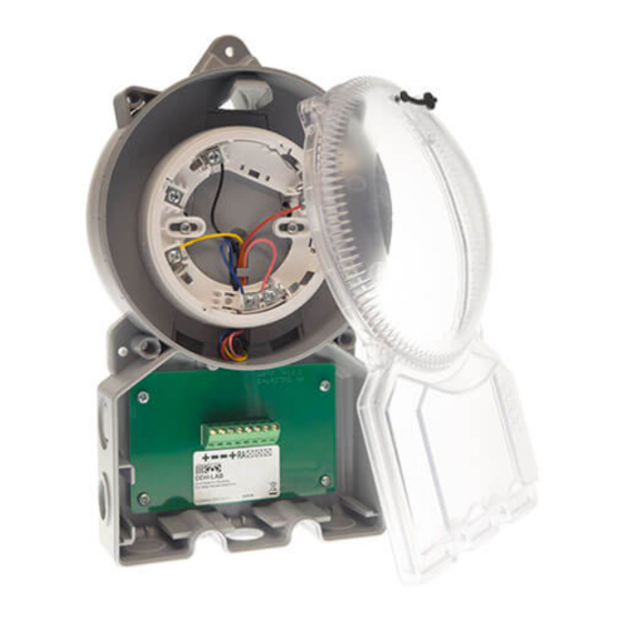
DUCT DETECTOR HOUSING FOR ALTAIR SMOKE DETECTORS
This Duct Detector Housing (DDH) is designed to provide capability to mount the indicated Altair smoke detector. When installed correctly it will
then allow monitoring of airflow in heating and ventilation ducts for fire combustion products. The DDH must be fitted with a Altair intelligent smoke
detector linked to a compatible control panel and a suitable sampling tube installed as shown. DDH has been designed to allow optimum airflow
through the detector and it is recommended for installations in ducts with low airflow and with an air speed between 0.5 m/s and 20 m/s.
CHARACTERISTICS
- Easy to install
- Installer friendly cabling
- Simple servicing and maintenance
- Single tube air sampling system
- Sampling tube with innovative design
- Sampling tube easy to mount
- Test hole positioned on cover.
Compatible detectors: A1000 (Altair smoke detector)
The air sampling tube is supplied in three lengths: 0.6 m (DDH-ST0.6)
1.5 m (DDH-ST1.5)
2.8 m (DDH-ST2.8)
If the ventilation duct is wider than 0.6 m the sampling tube should
penetrate the whole duct.
Mounting bracket (for insulated / circular ducts): DDH-BR
Weight: 660 g (without the detector installed)
INSTALLATION
The sampling tube is made of aluminium and can easily be shortened to suit the diameter of the duct.
With insulated or circular ducts use the DDH mounting bracket.
MOUNTING AND POSITIONING
The DDH can be installed on any side of the duct.
We recommend that the DDH is mounted at a proper distance from heating, cooling, humidity or similar devices, equal to the positioning standard
of flow meters.
A distance of 3 times the duct diameter should be left before a damper, filter or change of the duct direction.
A distance of 5 times the duct diameter should be left after a damper, filter or change of the duct direction.
The DDH shall be installed pointing towards the air flow direction
Air flow direction
Example of location after
change of duct direction
Hydraulic diameter
Circular duct
Rectangular duct
List of sources of interference:
- fan
- damper
- silencer
- battery
- air handling unit
- duct bend
- duct branching
- duct narrowing or expansion.
Drill a hole in the duct:
1
- Without bracket, ø 38 mm.
- With bracket, ø 51 mm (see point 10).
2
Do NOT cut this end!
ARGUS SECURITY S.R.L. - Via del Canneto, 14 - 34015 - Muggia (TS) - Italy
DDH-LAB
DDH dimensions in mm
Example of location
Air inlet
before air inlet
DDH
DDH
Fan
Duct bend
DDH
DDH
DDH
DDH
Air handling unit
Duct branching
1. Measure the diameter of the duct.
2. Shorten the pipe, if necessary. The pipe should penetrate
approx. 90% of the width of the duct. NOTE! See point 9.
3. Insert the end plug.
End plug
3
4
5
DDH
Return air
Inlet air
6
Detectors can be addressed by using a special hand-held programming unit or they can be
automatically addressed from the control panel after installation completion; note that the
automatic addressing feature must be implemented by the control panel manufacturer: check the
panel's literature to determine whether this operation can be performed.
Addresses may be selected through a 1 to 240 range and each device on the loop must have a unique
address.
7
www.argussecurity.it
info@argussecurity.it
1. Insert the pipe into the bottom of the DDH.
2. Secure the pipe with the locking screw.
Locking screw
1. Mount the pipe and the DDH on the duct.
2. Secure the bottom of the DDH with the three provided screws; screw positions
are marked on the picture.
1. Remove the cover over the DDH (four screws).
2. Use a cable gland (PG13.5 or M20). The DDH is factory prepared
with one cable opening. In case more than one opening is
needed, carefully remove the round plastic wall in the selected
entry and insert a cable gland. If the factory prepared opening is
not used, it must be properly sealed.
Ensure all glands are fully sealed and no openings remain to
allow air leakage which may prevent effective operation.
3. Connect the external cables according to the wiring
diagram.
1) Position the detector centrally on the DDH adaptor base
ensuring it is level.
2) Rotate clockwise applying gentle pressure. The detector will
drop into its keyed location.
3) Continue to rotate clockwise a few degrees until the detector
has fully engaged in the adaptor base.
4) When the detector is firmly engaged,
check the alignment of the raised
reference marks on the detector and
on the base.
INSTALLATION ON THE DUCT
ELECTRICAL INSTALLATION
SETTING THE ADDRESS
INSTALLING THE DETECTOR
L20-DHLBX-0001 (v0.3)
RN
Advertisement

Related Manuals for Argus Security DDH-LAB


Summary of Contents for Argus Security DDH-LAB
- Page 1 4) When the detector is firmly engaged, End plug check the alignment of the raised reference marks on the detector and on the base. ARGUS SECURITY S.R.L. - Via del Canneto, 14 - 34015 - Muggia (TS) - Italy www.argussecurity.it info@argussecurity.it L20-DHLBX-0001 (v0.3)
- Page 2 Product must be returned via your authorized supplier for repair or replacement together with full information on any problem identified. Full details on our warranty and product’s returns policy can be obtained upon request. ARGUS SECURITY S.R.L. - Via del Canneto, 14 - 34015 - Muggia (TS) - Italy www.argussecurity.it info@argussecurity.it...
Need help?
Do you have a question about the DDH-LAB and is the answer not in the manual?
Questions and answers