Advertisement
Quick Links
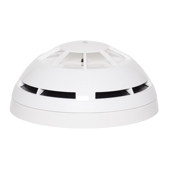
GENERAL DESCRIPTION
The wireless optical smoke detector samples the air in the protected area. An alarm condition is raised when the detected environmental
smoke quantity exceeds the alarm threshold.
Picture 1
DETECTOR VISUAL LED INDICATOR
The wireless optical smoke detector is equipped with a LED that provides visual
indication for functional modes, battery faults and other fault types (see table 1).
LINKING THE DEVICE TO THE SYSTEM
This detector must be linked to the fire security system before installation; specifi-
cally it must be linked to its translator or expander module as per installation plan.
For more detailed information about wireless linking refer to "Guide to
wireless system installation" document (APN-W0001) or refer to your sys-
tem supplier.
This manual gives the specific linking procedure applicable only to this detector.
STANDARD LINKING PROCEDURE
When the Wirelex program or the translator module is waiting for this device to be
linked, perform the following actions:
1) Check that the link switch is on the "ON" position.
2) Extract the isolating tab from the back of the detector (picture 2).
Device LED will indicate "operating mode".
3) Move the switch in position "1" to start the linking phase.
Device LED will indicate "linking mode".
Picture 2
Extract the isolating tab from the
back of the detector
ARGUS SECURITY S.R.L. - Via del Canneto, 14 - 34015 - Muggia (TS) - Italy
SG100
WIRELESS OPTICAL SMOKE DETECTOR
LED SIGNAL MEANING
"Power up mode".
The isolating tab has just been
extracted or the main battery
has just been inserted.
"Linking mode".
Linking phase has been
started.
"Linking failure mode".
"Normal operating mode".
"Alarm mode".
Device unpowered.
Main battery fault (low charge)
Secondary battery fault (low
charge)
Both batteries fault
Tamper fault
Other fault type
4) If linking went ok, the LED will indicate "normal operating mode".
The link switch MUST be left on "1" from now!
5) If linking failed, the LED will indicate "linking failure mode"; perform the
"RECOVERY LINKING PROCEDURE".
928k/01
1. Detector
2. Mounting base
3. Visual LED indicator
4. Link switch
5. Tamper switch
6. Batteries housing
7. Secondary battery
8. Main battery
9. Battery cover
LED VISUAL SIGNAL
Green LED blinks;
Orange LED on for 2 seconds;
Red LED blinks.
Green LED blinks;
Red LED blinking 1 second on
and 0.1 second off;
Green and red LED alternat-
ing for 1 second.
Red LED continuously on.
LED off.
Red LED blinking: 0.5 second
on and 0.5 second off.
LED off.
Orange blinking: 0.1 second
on and 5 seconds off.
Green LED blinking: 0.1
second on and 5 seconds off.
Sequential orange-green LED
blinking: 0.1 second on and 5
seconds off.
LED off.
Sequential orange-green LED
blinking: 0.5 second each
colour.
www.argussecurity.it
Table 1
Advertisement

Related Manuals for Argus Security SG100


Summary of Contents for Argus Security SG100
- Page 1 The link switch MUST be left on “1” from now! 5) If linking failed, the LED will indicate “linking failure mode”; perform the “RECOVERY LINKING PROCEDURE”. ARGUS SECURITY S.R.L. - Via del Canneto, 14 - 34015 - Muggia (TS) - Italy www.argussecurity.it...
- Page 2 RECOVERY LINKING PROCEDURE From the moment you switch on “1” to the moment linking comes to an end, the detector 1) Uninstall the battery housing cover. must be only a few inches away from the translator or expander 2) Take out the main battery from its housing. you are linking to.
- Page 3 4) Wipe the exterior housing of the detector with a clean, damp, lint-free cloth to remove any surface film that can later attract airborne contaminants. 5) Install the detector onto its base again. 6) Test the detector. ARGUS SECURITY S.R.L. - Via del Canneto, 14 - 34015 - Muggia (TS) - Italy www.argussecurity.it...
- Page 4 From –10 °C to +55 °C * When a low battery condition is indicated, both, main and secondary, batteries must be changed altogether. ** Check latest version of document TDS-SG100 for further data, obtainable from your supplier. WARNINGS AND LIMITATIONS Our devices use high quality electronic components and plastic materials that are highly resistant to environmen- tal deterioration.
Need help?
Do you have a question about the SG100 and is the answer not in the manual?
Questions and answers