Advertisement
Quick Links
www.dasstech.com
DASS Tech Co., Ltd.
Customer Ser vice Center
1588-7468
Main Phone of Headquar ter
043-218-5670
(FAX)
043-218-5671
E-mail
webmaster@dasstech.com
The specifications of the product are subject to change without notice due to quality improvement, etc.
Headquarter: 109, Yangcheongsongdae-gil, Ochang-eup, Cheongwon-gu, Cheongju-si, Chungcheongbuk-do,
28118, Republic of Korea (in Science Park of Ochgang)
http://www.dasstech.com
Ver 1
.
1
Manual for Use and Installation
DASSTECH Solar Photovoltaic
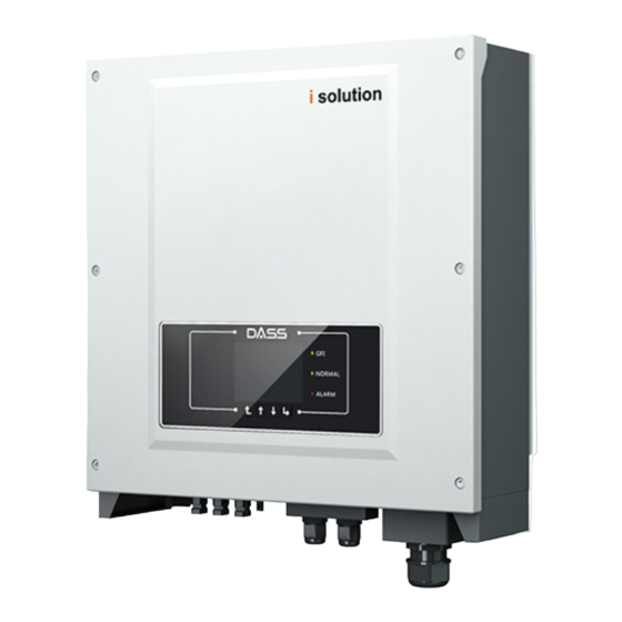
DSP-3315i-ODS
Version 1.1
Advertisement

Related Manuals for DASS Tech saleaf DSP-3315i-ODS


Summary of Contents for DASS Tech saleaf DSP-3315i-ODS
- Page 1 Manual for Use and Installation DASSTECH Solar Photovoltaic DSP-3315i-ODS Version 1.1 DASS Tech Co., Ltd. Customer Ser vice Center 1588-7468 Main Phone of Headquar ter 043-218-5670 (FAX) 043-218-5671 E-mail webmaster@dasstech.com The specifications of the product are subject to change without notice due to quality improvement, etc.
- Page 2 DASS TECH does not declare or guarantee any content in this document except there are other contractual stipulation.
-
Page 3: Table Of Contents
DSP 3315i-ODS DSP 3315i-ODS User manual User manual Symbols Safety instructions and warnings Intended grid types Interface and Dimensions Protection units Packing Materials 10.1 Standard warranty period DASS TECH inverter 10.2 Extended warranty period 10.3 Invalid warranty clause DRMs Functions... -
Page 4: Symbols
1.1 Symbols ,incorrect operation may cause property loss, equipments damage or personal injury. DASS TECH inverter has some safety related symbol, please make sure you have read and understand these symbol content before you install this equipotent. 1. Inverter can be installed only by professional electrician or electrical engineer according to local standard and regulations. -
Page 5: Intended Grid Types
DSP 3315i-ODS DSP 3315i-ODS User manual User manual 2.2 Interface and Dimensions 2.1 Intended grid types DASS TECH inverter 2 3 4 5 6 7 8 DASS TECH inverter DASS TECH inverter DASS TECH inverter DASS TECH inverter 1, DC Switch... -
Page 6: Protection Units
DSP 3315i-ODS DSP 3315i-ODS User manual User manual 2.3 Protection units A. RCMU When inverter'e leakage current exceeds safety requirement, inverter will stop generation B. Grid abnormal protection When inverter detects the grid or voltage is out of range , inverter will stop generation. Inverter will restart to generation automatically when the grid is normal again C. -
Page 7: Packing Materials
DSP 3315i-ODS DSP 3315i-ODS User manual User manual 3.2 Tools 3.1 Packing Materials DASS TECH inverter 3PCS 3PCS DASS TECH inverter. 3PCS 3PCS 3PCS 6PCS DASS TECH inverter... -
Page 8: Dass Tech Inverter
DSP 3315i-ODS DSP 3315i-ODS User manual User manual DASS TECH inverter. Diameter 2.0mm Diameter 5.0mm Installation position requirements 1.It should be easy to cut off the power supply 2.The wall should have enough strength to support inverter 3.Can not be touched by child... - Page 9 DSP 3315i-ODS DSP 3315i-ODS User manual User manual Figure 3-3 Many DASS TECH inverter installation...
- Page 10 DSP 3315i-ODS DSP 3315i-ODS User manual User manual 3.4 Installing the DASS TECH inverter Figure 3-4 1. Make sure the inverter DC switch is in OFF status 2.Check if the grid voltage and frequency are in correct range 3.If the PV panel is thin-film panel , a transformer(1.25 times as inverter capacity) should be added at AC side 4.PE cable should be thicker than 4mm and reliable,...
- Page 11 Cross area DSP 3315i-ODS AC cable installation steps DASS TECH inverter is three phase output inverter, it complies with related on-grid standard and safety requirements. Connect OT terminal to AC connector according to the painting then fix the water-proof cover.
- Page 12 DSP 3315i-ODS DSP 3315i-ODS User manual User manual DASS TECH inverter DASS TECH inverter DASS TECH inverter.
- Page 13 DSP 3315i-ODS DSP 3315i-ODS User manual User manual 4-11 DASS TECH inverter TERMINAL TERMINAL TERMINAL DASS TECH inverter TERMINAL 4-10 DASS TECH inverter DASS TECH inverter 4-12 TERMINAL The distance between WIFI and Ethernet router should be less than 100m.
- Page 14 DSP 3315i-ODS DSP 3315i-ODS User manual User manual 4-16 4-15 4-13 4-15 4-13 4-14 DASS TECH inverter...
-
Page 15: Drms Functions
DASS TECH inverter 4-17 4.5 DRMs Functions 4-17 4.5.1 DASS TECH inverter have five TTL input and one 5V Power output witch provided the DRMs function. The Ports are RG/0,CL/0, DRM1/5, DRM2/6, DRM3/7, DRM4/8, and GND ,5V,as shown below :... - Page 16 DSP 3315i-ODS DSP 3315i-ODS User manual User manual 4.5.2 PINs Physical Function Discription: 2. Provided the DC Power through the PV Pannel until the LCD is working; The DRMs function allocation is shown in below Table: 3. Set inverter country code as 02(Australia) in Enter Setting>Set Country Code(password 0001) ;...
- Page 17 Please consult qualified electrical engineer or personnel from electrical safety authorities about this. DASS Tech Co., Ltd is not responsible for any consequences arising out of incorrect country code selection. If the inverter indicates any other fault, please refer to part 7——error messages for help.
- Page 18 DSP 3315i-ODS DSP 3315i-ODS User manual User manual 180V remote off 160V...
- Page 19 DSP 3315i-ODS DSP 3315i-ODS User manual User manual Clear Energy On-Off Control Enset Country Set Energy Set Address Set Inputmode Set Language Set StartPara Set SafetyVolt Set SafetyFreq Set Insulation Set Reactive Set PowerDerat 17. PE Linecontrol 18. Set RefluxP 19.
- Page 20 (default:0001) Enset Country 6 . Enset Country 6. Enset Country User can check current country code in SystemInfo>>5. Country. Note: Country code changing will take effect after inverter reboot. Set Energy 7 . Set Energy Ukraine DASS TECH inverter 34-49...
- Page 21 "2.disable DRMS0", and finally press the OK button to set it successfully. Autotest Fast Step 1: During the normal operation of our DASS TECH inverter, press “back” button (the leftmost button) to enter the main menu interface. Step 2:Press “Confirm” button (the rightmost button) to enter the “Enter Setting”...
- Page 22 Auto Test OK! Wait for another test Autotest STD Testing 27.S2... Step 1:during the normal operation of our DASS TECH inverter,press “back”button (the Wait leftmost button) to enter the main menu interface Step 2:Press "Confirm"button (the rightmost button)to enter the "setting"menu interface.
- Page 23 DSP 3315i-ODS DSP 3315i-ODS User manual User manual Test 59.S1 OK! 81>S2:49.9Hz 89ms Press “Down” button to see the test results Wait for another test Testing 81<S1... 59.S1:230V 183ms Wait for another test Wait Testing 59.S2... Test 81<S1 OK! Wait Press “Down”...
- Page 24 Power factor Power factor Safety Paras 8.Power factor 9.MPPT Scan 0715 User can check the current software version in SystemInfo>>3. SoftVersion. DASS TECH inverter waterproof waterproof DASS TECH 0715 waterproof User can check the current software version in SystemInfo>>3. SoftVersion.
- Page 25 PV string, thus the voltage(Vmp) of the PV string is lower than the minimum operating voltage of DASS TECH inverter. If yes, adjust the number of series connected PV modules to increase the voltage of the PV string to fit the input voltage range of DASS TECH inverter.
- Page 26 If no, please contact DASS TECH technical support. Check the input mode(parallel mode/ independent mode) setting of DASS TECH inverter according to Section 4.5 of this user manual. If the input mode is correct, turn OFF the “DC switch”, wait for 5 minutes, then turn ON the “DC...
- Page 27 User manual User manual ID91 Fan1 alarm Fan 1 fault Check the external fan with blue cable, if it is fault , contact DASS TECH to replace it. Id92 Fan2 alarm Fan 2 fault Check the external fan with red cable, if it is fault , contact DASS TECH to replace it.
- Page 28 DSP 3315i-ODS DSP 3315i-ODS User manual User manual Output parameters (DC) Technical Data DSP 3315i-ODS Rated output power 15000W 9.1 Input parameters (DC) Max apparent power 16500VA Max output current 3*24A DSP 3315i-ODS Technical Data Output voltage range 230/400V; 184-275V Max.
- Page 29 Common parameters check with DASS TECH service team. Monitoring devices (WiFi card, Ethernet card, GPRS card, Dimension(W*H*D)[mm] GPRS kit) are not included in the on-site service range, but DASS TECH could provide remotely 540*452*202 service and replacing service. Weight [kg]...
Need help?
Do you have a question about the saleaf DSP-3315i-ODS and is the answer not in the manual?
Questions and answers