
Related Manuals for DASS Tech Soleaf DASS 100i


Summary of Contents for DASS Tech Soleaf DASS 100i
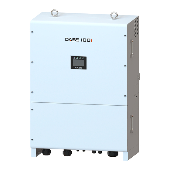
- Page 1 Operation and Installation Manual DASSTECH Photovoltaic Grid- Connected Inverter [Grid connected type Photovoltaic Inverter] DASS 100i [DSP-33100E-OD-HV] Version 1.0...
-
Page 2: Table Of Contents
Table of Contents ......................3 Precautions for Safety…. 1.1 Symbols Used in the Manual...........................4 1.2 Symbols Used in the Inverter…………........................5 1.3 Precautions while Operating.………........................6 ........................8 Product Overview ...............................8 Basics……… ........................8 Appearance of the Product ..........................9 Verification of the Product ........................10 Configuration of the Product ........................12 Dimensions of the Product ....................13... - Page 3 Design Guide of High Voltage Transformer for Central Inverter Design Guide....30 4.1 Technical Properties..............................30 4.2 Requirements of the mid-voltage power transformer connected to the (single) central inverter…………………………………………………………………………………………………………………………………….31 4.3 Requirements of the mid-voltage power transformer connected to the (double) central inverters………………………………………………………………………………………………….…………......34 4.4 Winding Technology ............................37 ..........................39...
-
Page 4: Precautions For Safety
1. Precautions for Safety Precautions for safety aim for safe and correct operation of the products by preventing accidents or hazards in advance, so you must follow them at all times. In order to properly and safely use the functions of DSP inverter series, read the manual carefully. -
Page 5: Symbols Used In The Manual
1.1 Symbols Used in the Manual The meaning of the symbols used in the manual is as follows: Danger indicates a hazardous situation which, if not avoided, will result in death or serious injury Warning indicates a hazardous situation which, if not avoided, can result in death or serious injury Caution indicates a hazardous situation which, if not avoided, can result in minor or moderate injury... -
Page 6: Symbols Used In The Inverter
1.2 Symbols Used in the Inverter The meaning of the symbols used in the inverter is as follows: Symbol Description Do not lift up or move the product alone. Keep the connection requirements of secondary protective conductor. Refer to Ground Connection in page 26. The product can be heated during the inverter’s operation. -
Page 7: Precautions While Operating
1.3 Precautions while Operating Do not operate the product when the front cover is opened. It can cause electric shock as the high-voltage terminals or live parts can be exposed. Do not operate the switch with wet hands. It can cause electric shock. - Page 8 Do not install the product near any flammable materials If the product is installed with flammable materials or attached near flammable substance, it can cause a fire. Disconnect the input power (solar cells) and output power (AC system power) in the inverter during inverter failure.
-
Page 9: Product Overview
2. Product Overview 2.1 Basics If the inverter is operated incorrectly, it can prevent normal operation or reduce a lifespan of the product. In the worst case, the inverter can be broken or incur fatal damage to human bodies. Therefore, please read carefully and understand thoroughly the operation and installation manual prior to the use. -
Page 10: Verification Of The Product
2.3 Verification of the Product Please check the name plate at the side of the main product body whether inverter type and rated output are matched with the ordered product details once the inverter is taken out of the packaging box. In addition, check whether there is any damage during transportation. Inverter TYPE ... -
Page 11: Configuration Of The Product
2.4 Configuration of the Product Front view ... - Page 12 Side view 명판 Rear view ...
-
Page 13: Dimensions Of The Product
⑦ ④ ③ ① ② ⑤ ⑥ ⑧ Bottom view Item Name Description ① PV(+) Input Port Input PV(+) cable gland ② PV(-) Input Port Input PV(-) cable gland ③ COM1, COM2 485 communication (IN, OUT) ④ Wifi cable (option) ⑤... -
Page 14: Configuration Of The Photovoltaic System
2.6 Configuration of the Photovoltaic System With arranging necessary equipment correctly, the inverter shall be connected well. With the wrong system configuration and connection, it can cause abnormal operation or reduce a lifespan of the product seriously. In the worst case, the inverter can be damaged, so please use the product well according to the contents and precautions in the manual. -
Page 15: Features Of The Product
2.7 Features of the Product High-efficiency power conversion PWM method with IGBT semi-conductor device is applied and the high-efficiency of 98% or higher can be achieved at the rated power. Digital control The system is controlled efficiently through the high-performance digital control and it can be checked through LCD keypad to monitor and display the operation of the inverter including input/output status, also fault conditions to terminate the operation. -
Page 16: Installation
Simplicity of operation The inverter is designed to display the status in real time through the front LCD screen. 3. Installation 3.1 Transportation Please transport the product correctly according to the weight of the product. Do not stack the product beyond the restricted limit. ... -
Page 17: Installation Place
Please check the outer appearance of the product whether there are no fault appearances found. Do not drag or throw the inverter. Since the inverter is a precise apparatus, do not drop the inverter or give any strong impact. 3.2 Installation Place Caution Please install the product at a place where the following conditions are met. -
Page 18: Cautions While Installation
3.3 Cautions While Installation Please install the product according to the contents in the manual. The installation place should be clean at all times and can be accessed safely without using auxiliary means such as lifting platform or foothold. Otherwise, service work may be limited. The connecting part (bottom surface of the inverter) should be directed to the below. - Page 19 Be sure to use the exclusive bracket, and use caution due to the sharp part. Prior to installing the inverter, DC switch installed at the lower end of the inverter should be OFF. If it is ON, it can be a cause of a failure during installation. Upon installation completion, the inverter should be ON, and then make the inverter operated.
-
Page 20: Installation Method
3.4 Installation Method Please refer to the below photo for the installation method. After the fixing bracket is installed, the inverter is placed on the bracket and fastened by the bolts. Caution At least 4 or more persons must install the inverter during lifting or fixing it to the bracket. Because the product is heavy, pls. - Page 21 Mark the locations of drill holes by using a fixing bracket (inner wall bracket) and bracket drawings provided along with the inverter. Please refer to the drawing as below to make holes (3 points) on the location for fixing a bracket.
-
Page 22: Block Diagram
3.5 Block Diagram <DSP-33100E-OD-HV Block Diagram> 3.6 Precautions during Wiring Incorrect terminal connection can cause damage to the inverter. Please be careful for polarity (+/-) during DC connection. Distinguish carefully grounding and power lines during connecting AC connectors. ... - Page 23 Separate the bottom bracket from the body as above. For wiring, pls. work according to the following procedures Put the wire to be used through a cable gland Put the wire through the bottom bracket. Wiring the wire to applicable components(DC breaker, AC breaker, Grounding wire and etc.) After finishing wiring, assemble the bracket to the body.
-
Page 24: Dc Connection
Capacity Grounding wire dimension(mm²) 1.5 ~ 3 kW 5 kW or higher 100 kW or higher 25.0 Please check the maximum input voltage of the inverter and output voltage of the solar cell array. If the output voltage of the solar cell array exceeds the maximum input voltage of the inverter, critical damage can occur in the inverter. -
Page 25: Ac Connection And Grounding Connection
3.8 AC Connection and Grounding Connection AC Connection ⑤ Cover can be opened by loosening 2 bolts in the bottom part. ⑥ AC circuit breaker can be found by opening the cover as above. ⑦ Please use a wire of 70SQ for AC wiring pls. - Page 26 ⑧ An order of AC circuit breaker is R, S, T and N form the left side. ⑨ Pls. use only dedicated screw connected to AC circuit breaker ⑩ When the cable is connected to AC circuit breaker, care should be taken that the cable and terminal do not have a phase-to-phase short-circuit among R, S, T, and N.
- Page 27 Grounding connection ① Please use dedicated grounding wires when grounding wire is done. ② Use copper wire for grounding cable. ③ A thickness of grounding wire should be 25SQ or thicker. ④ Please press a terminal against the grounding wire and connect the wire to grounding bus bar in the bottom part of the inverter.
-
Page 28: Rs485 Communication Connection
3.9 RS485 Communication Connection ① In case of parallel connection, pls. use two cable glands for communication. ② Open the cover in the bottom part of the inverter. RS485 Communication terminal... - Page 29 ③ Pass the communication power wire (3~6.5mm) through the cable gland and connect the communication line [+] to BUS+ of RS485 connector, the communication line [-] to BUS-, respectively. ④ In case of parallel connection, implement parallel connection for 485communication by using 485 IN, OUT.
-
Page 30: Active Voltage Control Setting
3.10 Active Voltage Control Setting Active voltage control communication terminal (Using KEPCO KDN device(DER-AVM)) ① System ID Number should be set according to the below method during the communication use. When ID is not assigned, the value is set to 0 by default. (Menu button –... -
Page 31: Technical Properties
4. High voltage transformer design guide for a central inverter For new energy, the warranty is only applied to high-voltage transformers installed in accordance with the guideline provided with the application note. The photovoltaic inverter is classified into two types: transformer and non-transformer types. Since a non-transformer type inverter has no transformer in the inside in contrast with transformer-type inverter, a medium voltage (MV) transformer should be designed in accordance with the guideline when it is connected to the external high-voltage transformer. -
Page 32: Requirements Of The Mid-Voltage Power Transformer Connected To The (Single) Central
3. The low-voltage winding of the transformer shall be designed for voltage that can produce a voltage gradient dV / dt of up to 500V / µs reference to the ground. The line-to-line voltage waveform is a sine wave. 4. A shield winding that is grounded to the tank is needed between the low-voltage and high-voltage windings. - Page 33 This transformer shall comply with the following technical specifications. Equivalent series impedance between low-voltage and high-voltage windings: The equivalent series impedance Z(%) of the transformer shall be 6%. The impedance voltage allowable criteria of 5.4% to 6.6% shall be maintained. This value can be determined when the voltage in other low-voltage winding increases until the high-voltage winding is short-circuited and a nominal current flows.
- Page 34 A neutral point is not needed in the low-voltage side. Nonetheless, if a neutral point appears in the low-voltage side, this neutral point shall not be connected or grounded. A two-winding transformer where winding changes in each of the high-voltage and low-voltage ...
-
Page 35: Requirements Of The Mid-Voltage Power Transformer Connected To The (Double) Central Inverters
4.3 Requirements of the mid-voltage power transformer connected to the (double) central inverters The transformer in the figure allows only a double stack (four-winding) transformer and a three-winding transformer with LHL winding. In such MV transformer, a high-voltage winding is placed between two low-voltage windings. - Page 36 Equivalent series impedance between low-voltage windings: The equivalent series impedance Z(%) of two low-voltage windings shall be 10%. The allowable error limit of the impedance voltage shall maintain 9% to 11%. This value can be determined when the voltage in other low-voltage winding increases until one of the low-voltage windings is short- circuited and a nominal current flows.
- Page 37 The equivalent series impedance Z(%) of the double stack (four-winding) transformer: The contents of Articles 1 and 2 can be summarized that the equivalent series impedance Z(%) of the double stack (four-winding) transformer can be expressed as follows: ZL refers to the equivalent series impedance of the low-voltage winding, and ZL refers to the equivalent series impedance of the high-voltage winding.
-
Page 38: Winding Technology
4.4 Winding technology The MV transformer that is connected to the photovoltaic inverter without transformer shall be designed as a section winding transformer. Single layer winding transformer Case 1. Double stack Case 2. Triple stack Case 3. Triple stack (LHL) - Page 39 LVW : Low voltage winding HVW : High voltage wingding Multi-layer winding transformer Case 1. LLH Case 2. LLLH...
-
Page 40: Operation
5. Operation 5.1 Checklist prior to Operation ① Once the connection is complete between PV cable and AC cable, the inverter is ready for startup. ② Turn the DC switch in the lower part of the inverter to the ON direction then, Turn the DC switch to the ON direction. -
Page 41: Display Window Screen
State LED Description Its displays the input state from the solar cell module. GRID It Displays if the grid is run normally. It displays if the inverter is run normally. FAULT It displays if an error is generated in the inverter. The LCD specification in the display window is 128x64 GRAPHIC LCD. - Page 42 100.0 kW PV Vtg : 658.0 V PV Cur : 152.0 A ■ RUN /STOP : Present operation status, 100.0kW : Present power ■ PV Voltage : Input PV voltage ■ PV Current : Input PV current 100.0 kW Line R Vtg : 380.0 V Line S Vtg : 380.0 V...
-
Page 43: How To Operate
5.4 How to Operate Checklist prior to the operation Check the status of wiring in the inverter and its installation. In particular, check if the input polarity of solar cells is connected accurately or if the connection of the grid line is connected correctly. Supply the DC power of solar cells to the inverter. -
Page 44: Functions
6. Functions 6.1 Description of Functions Grid monitoring Normal or fault state in the grid voltage is determined by a difference in voltage (Fault high voltage and Fault low voltage) compared to a normal voltage. If the value is larger or smaller than the pre-set value, the inverter is stopped. - Page 45 Modification of set values Parameter values can be modified using the internal keypad during inverter stop. Caution! Please contact the main office if you need to modify parameter values. Initialization There are two initializations: parameter and fault initializations. Parameter initialization sets all parameters and optional functions to factory default values while fault initialization removes all fault records in the past and makes the system to ready-state.
-
Page 46: Symptoms Of Warning And Fault
6.2 Symptoms of Warning and Fault If a warning occurs in the product, this is displayed in the screen. The product displays a system fault and stops the operation. The product displays a grid fault and stops the operation. ... - Page 47 Negative phase In case of negative phase, the inverter does not count for running. Grounding fault protection If a leakage current occurs due to grounding fault, the system is stopped. Grid fault protection Upon the fault occurrence in the grid power, the system is stopped. (Grid over-voltage protection, grid under-voltage protection, grid over-frequency protection, and grid under-frequency protection) PWM control fault...
-
Page 48: Types Of Faults And Corrective Actions
6.4 Types of Faults and Corrective Actions Type of Display Cause of Error Corrective Action Error InsDC-Link DC_LINK Overvoltage of DCP, Contact the service center. Overvoltage AvgDC-Link DCN, DC_LINK DC_LINK Undervoltage of InsDC-Link Contact the service center. Undervoltage DCP, DCN, DC_LINK Operate the inverter after inspecting the solar If the solar cell Input... - Page 49 If output of the InsLine x Output inverter is in over- Contact the service center. overcurrent AvgLine x current state Line x OC2, Inverter internal fault Contact the service center. FAULT x UVLO Relay Relay_Open Relay fuse and failure Contact the service center. FAULT Relay-Short Communication...
-
Page 50: Types Of Warnings And Corrective Actions
PHASE Negative phase Negative phase Rewire the output cable. REVERSE InsLine xN Grid (phase) Grid R, S, and T phase Contact the service center. overvoltage AvgLine xN overvoltage Grid (phase) Grid R, S, and T phase AvgLine xN Contact the service center. undervoltage undervoltage 6.5 Types of Warnings and Corrective Actions... -
Page 51: Failure Repair
6.6 Failure Repair Check whether or not the inverter has a fault. Check the date, time, and failure display description when the product is broken. The following items are checked and service repair is requested. Model name Manufacture No. -
Page 52: Maintenance And Cleaning
7. Maintenance and Cleaning Be sure to carry out maintenance of the inverter regularly. Recommended Service work 내용 service period - Remove fan dust at the right side of the inverter 6 months Cleaning - Remove vent dust at the left side of the inverter - Remove fan dust at the right side of the inverter Cleaning - Remove vent dust at the left side of the inverter... -
Page 53: Product Specifications
8. Product Specifications Model name DSP-33100E-OD-HV DC. Vmax. PV 1000Vd.c Operating voltage range 580 ~ 980Vd.c MPPT voltage range 580 ~ 800Vd.c Rated voltage 650Vd.c Operating start voltage 650Vd.c Max. short-circuit current 200A Input per MPPT route Max. inverter back-feed current to the array Maximum input current 178A... - Page 54 Model name DSP-33100E-OD-HV Cooling method Forced-air cooling Protection structure IP 65 Noise Less than 70 dB Structure Dimension(W x H x D) 650mm x 910mm x 360mm Weight 85kg Communication interface RS485 Input overvoltage Output short-circuit DC overvoltage protection Inverter Insulation monitoring Inverter overheat protection Relay fault detection...
-
Page 55: Warranty
• In case the product was repaired or revised at unofficial service center/man, not designated • In case of without the nameplate of DASS Tech • In case any failure occurs after the user dismantled, repaired or replaced our products •... - Page 56 Customer service +82-1588-7468 Tel: +82-43-218-5670 Fax: +82-43-218-5671 Headquarters: DASS Tech Co., Ltd. 81, Yangcheongsongdae-gil, Ochang-eup, Cheongwon-gu, Cheongju-si, Chungbuk, Korea http://www.dasstech.com Ver. 1.0...
Need help?
Do you have a question about the Soleaf DASS 100i and is the answer not in the manual?
Questions and answers