
Subscribe to Our Youtube Channel
Related Manuals for EASEPAL EC-380B


Summary of Contents for EASEPAL EC-380B
- Page 1 中国·厦门蒙发利科技有限公司 Xiamen Comfort Science & Technology Co.,Ltd EC-380B Maintenance Service Manual MODEL: EC-380B Voltage specification:220-240V By Customer Service Department...
- Page 2 Model EC-380B Table of Contents I……Specifications ……………………………………………………….3 II.…..Appearance of the chair …………………………………………….4 III…. Name and functions of components (remote controller) …………...5 IV…..Malfunction catalog………………………………………………6~8 V……Troubleshooting flow chart……………………………………..9~13 VI……Maintenance of the back rest …………………………………14~19 VII…..Maintenance of the seat part ………………………………….20~24 VIII….Maintenance of the footrest …………………………………..25~28...
-
Page 3: Specifications
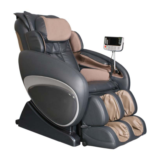
I. Specifications... - Page 4 II. Appearance of the chair Pillow Controller Backrest Shoulder massage Arm massage Backrest Pad Hip massage Seatpart Wheel Footrest Side panel...
- Page 5 III.Name and functions of components (remote controller) Remote controller Auto-program buttons Main control buttons The adjustment button Length auto adjustment for back body buttons for legrest Angle adjustment button Sensor receiver Back speed/Air intensity Manual back massage programs...
- Page 6 IV. Malfunction catalog Common Troubles and Maintenance Methods are listed as following: Serial Phenomenon Description Maintenance Methods Refer to The LCD isn’t illuminating: ① Replace Fuse(s). ① Page 24/20 ① Fuse(s) burn out ( the one ② (Ellipsis) ② Replace the power supply Is in the Power Source Box and ③&④...
- Page 7 ①Terminal or Wire Poorly ①Plug the terminal securely ①Page 23/18 ②&③ Contacts. or replace the wires. ②Down-stroke Photo- ②Replace Down-Stroke Page 19/8 ④Page 17/6.2 Electricity Subassembly Fails. Subassembly. No Rolling. ③Up-stroke Photo-electricity ③Replace Up-Stroke Sub- ⑤Page 23/18 Subassembly Fails. assembly. ④Rolling Motor Fails.
- Page 8 ①Plug the terminal securely. ①&②Page ① The terminals of foot rest ②Replace foot rest actuator. Foot rest cannot actuator and wires are 22/16 ③Replace main PCB. ③ Page 23/18 be raised or poorly connected. ②The foot rest actuator fails. lowered. ③Main PCB fails.
-
Page 9: Troubleshooting Flowchart
V. Troubleshooting flow chart Notes for repairing chair or replacing parts: ①Make sure the power is OFF before tearing down the wires, moving terminals or replacing parts. ②Semiconductors (such as IC and others) are very easy to be damaged by static, so when you touch the PCB, please make sure your body is grounding (by wearing a girding static ring), or your hands are touching with earthing grip (household electrical appliances putting to earth, such as fridges, washers and so on) to release all static of the body. - Page 10 2. No width switchover. Are the terminals of Width Inspection Board and main PCB connected securely? Connect securely. Width Inspection Board fails or not? Replace it. (Page 18/7.1) Replace main PCB. (Page 23/18) 3. No function(fixed-spot or partial) Connect securely. Are the terminals of main PCB connected securely? Replace Main PCB.
- Page 11 5. No kneading Are the terminals of kneading motor wire and main Connect securely. PCB connected securely? Kneading motor fails or not? Replace the motor. (Page 16/6.1) Width Inspection Board fails or not? Replace it. (Page 18/7.1) Replace main PCB. (Page 23/18) 6.
- Page 12 8. Actuator doesn’t work. terminals Are the terminals of foot rest Connect Connect reclining actuator and main actuator main securely. securely. PCB connected securely? connected securely? The reclining actuator Replace it. The foot rest actuator Replace it. fails or not? fails or not? (Page 21~22/15) (Page 22/16)
- Page 13 10. No gas charging in the outer coating of backrest The terminal of snuffle valves connected Plug terminals well well or not? Replace the snuffle valves The snuffle valves fail or not? (Page24/19) The terminal of the inflator pump Plug terminals well connected well or not? Replace the inflator pump The inflator pump fails or not?
- Page 14 VI. Maintenance of the back rest 1. Disassembly and replacement of back pad ① Find the zipper on the top of the back rest. Unzip it, then the back pad can be removed. ② There are two air hoses at the bottom of the back pad, pull out the connectors if a replacement needed. ③...
- Page 15 Lift the backrest at 90 degrees. A. Connecting rod (on the backrest) B. U stay fork of reclining actuator (on the seat) C. Flat head rivet D. Split pin 3. Replacement of cloth of the front cover ① Unfasten the zipper of the back pad, and lay the back pad on the seat pad. ②...
- Page 16 Attention: There are blocks between the front cover and back frame. Tool: a plus screwdriver Screws fastening the front cover to the back frame (6 PCS) 6. Replacement of the kneading, tapping and rolling motors Attention: The voltage of this massage chair is high and the motors are rotating in high speed, so make sure the power is OFF before disassembly.
- Page 17 6.2 Rolling motor(DC -24V) ① Disassemble the rear cover of the back rest, find the massage mechanism. ② Find the rail on the top of backrest and remove the screws to disassemble it. ③Disassemble the massage mechanism from the chair.(refer to 7.2) ④...
- Page 18 ⑤ Then the tapping motor can be removed and replaced. ⑥ Proceed in the reverse order of disassembly when assembly. Close-end wire connector of tapping motor 7. Maintenance of the massage mechanism 7.1Replacement of the Width Inspection Board Note:①If the massage mechanism is just kneading but no tapping or rolling, or it doesn’t work when power is on, and the main PCB is ok, in this we can think of that the Width Inspection Board fails.
- Page 19 Screws securing the mechanism Massage mechanism taken down Adjust the position of the massage mechanism and the width of the swinging arms 8. Replacement of up or down stroke photo-electricity assembly ① Disassemble the rear cover of the back rest. ②...
- Page 20 VII. Maintenance of the seat part 9. Replacement of the remote controller holder ① Pull out the remote controller from the holder. ② Remove the screw bolt tightening the holder. ③ Take away the holder from the support. ④ Install a new holder on the support. ⑤...
- Page 21 13. Replacement of the side board ① Disassemble the backrest from the chair ② Use a cable tie to unfasten the seat pad from the chair by the zippers. ③ Remove the screws (4pcs) securing the side board. ④ Lift the side boards at 90 degrees, then disassemble it from the chair. ⑤...
- Page 22 The connectors of the reclining actuator Flat head rivet securing the reclining actuator on the U stay fork 16. Disassembly of the foot rest actuator ① Disassemble the backrest from the chair, then find the reclining actuator ② Along the connecting wires of the reclining actuator to find the 2 connectors, then disconnect them.
- Page 23 ④ Find each end of the actuator is fixing on the U stay fork. There are two plastic bush rings in the hole. Attention: You must use the brace to support the footrest, avoid the footrest drop suddenly while pulling out plastic bush rings. ⑤...
- Page 24 19 Replacement of the inflator pump and the snuffle valves Inflator pump Snuffle valves ① Turn off the power, then lay the back rest on the seat pad and pull out the terminals of the back rest. ② Remove the screws(2pcs) securing the box of the main PCB on the iron tubes. ③...
- Page 25 IX. Maintenance of the foot rest 22. Replacement of the whole foot rest ① Turn on the power and raise the foot rest to the highest position. Then turn off the power. ② Remove the screws securing the front panel, take it away. ③...
- Page 26 wheel of belt on the shaft. ⑥ Proceed in the reverse order of disassembly when assembly. Note: You should adjust the position of the wheel of belt, so the two wheels are in the same plane. 24. Replacement of the front and back sensors of foot rest ①...
- Page 27 27. Replacement of upper outer coating of foot rest ① First you should disassemble the whole foot rest, and the cover of foot rest should be removed. ② Rotate the belt wheel to extend the foot rest to the longest position. Remove the screws tightening the upper part of the foot rest.
- Page 28 ⑥ Remove the screws fixing the lower part of the foot rest, then the outer coating can be removed. ⑦ Proceed in the reverse order of disassembly when assembly. Castor taken down Screws fixing the lower part...
- Page 29 Along with the amount of product amount increased, the shipment of spare parts will change similarly. Base of the shipment experience of prophase products, the project of spare part shipment of EC-380B prescribe as below: Spare parts amount ( according to the % of product Product amount amount)...
- Page 30 R133 +24V ROLLING R127 PWM3 PWM4 PMKT 5551 PMKT 5551 PMKT 5551 R130 9012 PTD2 9012 9012 R128 Title Size Number Revision Date: 16-Sep-2009 Sheet of PDF 文件使用 "pdfFactory Pro" 试用版本创建 www.fineprint.com.cn File: \EC-380B\EC-380-CEN-V1.0.Ddb Drawn By: 工作 文件 工程项 目...
- Page 32 EC-380B 端子与 IC 端口对照表 端子位号 对应端子 Pin 对应 IC 端口 对应有效电 对应功能 备注 脚 平 187 端子 20.5V~输入 187 端子 20.5V~输入 10.5V~输入 10.5V~输入 VH-2A 气泵电源输入 VH-3A 气泵电源输出 VH-3A RxD1 手控器连接端子 TJC3S-4A TxD1 高电平有效 PTA6 TJC3S-6A 高电平有效 PTA7 行程记数 跳变沿 PTB4 TJC3S-3A 跳变沿...
- Page 33 PTG1 预留 I/O 检测口 PTG2 TJC3S-6A PTA0 PTA1 高压交流输出(到 变压器输入口) VH-3A PTD6(对应 K2) 高电平有效 PTG4(对应 K1) 高电平有效 小腿推杆控制 VH-2A PTD7(对应 K4) 高电平有效 PTC2(对应 K3) 高电平有效 靠背推杆控制 VH-2A PTD4(对应 K5) 高电平有效 PTD5(对应 K6) 高电平有效 零重力推杆控制 VH-2A PTC1(对应 K7) 高电平有效 PTC0(对应 K8) 高电平有效 小腿伸缩电机控制 VH-2A PTD3(行走换向)...
- Page 34 预留 I/O 检测口 PTE6 预留 I/O 检测口 PTE5 预留 I/O 检测口 TJC3S-6A PTE4 预留 I/O 检测口 PTE3...
Need help?
Do you have a question about the EC-380B and is the answer not in the manual?
Questions and answers