Carel PlantWatchPRO Manual
I/o board
Hide thumbs
Also See for PlantWatchPRO:
- User manual (40 pages) ,
- User manual (56 pages) ,
- Assembly and installation (2 pages)
Advertisement
cod. +050001650 rel. 1.0 - 20.12.13
Scheda I/O - I/O board
PlantWatchPRO
Montaggio / Assembly
Fig. 1
Collegamenti elettrici / Electrical connections
Vista Superiore / Top view
Fig. 2
RL2
RL1
Fig. 3
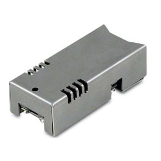
Il dispositivo PW3AREL000 è un modulo di espansione I/O per la gestione
di 2 uscite a relay. È da utilizzarsi unicamente come plug-in per il sistema
di supervisione: PlantWatchPRO (PW3*). Consente di gestire fino a 2 uscite
allarme o segnalazione remotata espandendo le funzionalità presentate nel
sistema stesso.
Montaggio del dispositivo
La scheda I/O viene montata posteriormente sui sistemi di supervisione
PlantWatchPRO sul relativo connettore femmina come in Fig.1. È a cura
dell'installatore la messa in sicurezza dell'apparecchiatura.
Collegamenti elettrici
La scheda deve essere abbinata al controllo facendo attenzione a quanto
segue:
• predisporre un sezionatore di sicurezza a monte sull'alimentazione
(230 Vac). in modo da poterla interrompere per eventuali ispezioni;
• collegare i carichi alle uscite a relay seguendo le indicazioni di Fig. 3;
• controllare le connessioni di potenza;
• utilizzare cavi aventi la sezione riportata nella tabella delle caratteristiche
tecniche.
Messa in servizio
Dopo aver verificato i collegamenti e alimentato il sistema, testare le uscite
relay.
Caratteristiche tecniche uscite a relay
tensione relè
corrente
cicli di manovra
isolamento rispetto la bassissima tensione
isolamento tra le uscite relè indipendenti
connessioni modello
tipo connessione
sezioni dei cavi
corrente max
Nota: il corretto dimensionamento dei cavi di alimentazione e di colle-
gamento tra lo strumento e i carichi è a cura dell'installatore.
Relay 2_Normal Open (NO)
Relay 2_COMM
Relay 1_Normal Open (NO)
Relay 1_Normal Close (NC)
Relay 1_COMM
CARATTERISTICHE GENERALI
250 V~
2 (2) A
100000
rinforzato
principale
estraibili a vite
relè
da 0,5 a 2,5 mm
5 A
GENERAL CHARACTERISTICS
The PW3AREL000 device is an I/O expansion module for managing 2 relay
outputs. It is used solely as a plug-in for the PlantWatchPRO (PW3*) super-
visory system. The device manages up to 2 remote alarm outputs or signals
so as to expand the functions available on the system.
Assembly
The I/O board is fitted at the rear of the PlantWatchPRO supervisory system
using the female connector provided, as shown in Fig.1. The installer is
responsible for ensuring safe installation of the device.
Electrical connections
The board must be connected to the control system keeping in mind the
following warnings:
• fit a safety disconnect switch upstream on the power supply line (230
Vac), to allow disconnection for checks or inspection;
• connect the loads to the relay outputs following the instructions in Fig. 3;
• check the power connections;
• use cables with the sizes shown in the technical specifications.
Commissioning
After having checked the connections and powered on the system, test the
relay outputs.
Relay output technical specifi cations
relay voltage
current
operating cycles
insulation from extra low voltage parts
insulation between independent relay outputs
model connections
type of connection
2
cable size
max current
Note: the installer is responsible for correct sizing of the power and
connection cables between the device and the loads.
250
2 (2) A
100000
reinforced
main
plug-in screw
relay
2
from 0.5 to 2.5 mm
5 A
Advertisement
Table of Contents

Related Manuals for Carel PlantWatchPRO


Summary of Contents for Carel PlantWatchPRO
- Page 1 The PW3AREL000 device is an I/O expansion module for managing 2 relay di 2 uscite a relay. È da utilizzarsi unicamente come plug-in per il sistema outputs. It is used solely as a plug-in for the PlantWatchPRO (PW3*) super- di supervisione: PlantWatchPRO (PW3*). Consente di gestire fino a 2 uscite visory system.
- Page 2 CAREL editate nel sito www.carel.com www.carel.com and/or by specific Carel reserves the right to modify the features of its products without prior e/o da specifici accordi con i clienti. agreements with clients. Carel si riserva la possibilità di apportare modifiche o cambiamenti ai propri prodotti senza alcun preavviso.
Need help?
Do you have a question about the PlantWatchPRO and is the answer not in the manual?
Questions and answers