Table of Contents
Advertisement
DKG-317 User Manual
DKG-317 MANUAL AND REMOTE START UNIT
Manual starting and stopping
Engine control
Generator protection
Built in alarms and warnings
3 phase genset voltage inputs
3 phase genset CT inputs
Engine oil pressure measurement
Engine coolant temperature measurement
Genset active power measurement
Genset power factor measurement
Periodic maintenance request indicator
Engine hours counter
Event logging
Statistical counters
Field adjustable parameters
RS-232 serial port
FEATURES
Free MS-Windows Remote monitoring SW:
-local, LAN, IP and modem connection
-monitoring, download of parameters
LED displays
Configurable analogue inputs: 2
Configurable digital inputs: 7
Configurable relay outputs: 2
Total relay outputs: 4
I/O expansion capability
Remote Start operation available
Survives cranking dropouts
Sealed front panel
Plug-in connection system for easy replacement
Small dimensions (165x125x48mm)
Low cost
V-01.19
Tel: +90-216-466 84 60
Fax: +90-216 364 65 65
datakom@datakom.com.tr
http://www.datakom.com.tr
(01.10.2009)
Advertisement
Table of Contents

Subscribe to Our Youtube Channel
Related Manuals for Datakom DKG-317


Summary of Contents for Datakom DKG-317
- Page 1 DKG-317 User Manual V-01.19 (01.10.2009) Tel: +90-216-466 84 60 Fax: +90-216 364 65 65 datakom@datakom.com.tr http://www.datakom.com.tr DKG-317 MANUAL AND REMOTE START UNIT FEATURES Manual starting and stopping Engine control Free MS-Windows Remote monitoring SW: Generator protection -local, LAN, IP and modem connection...
-
Page 2: Table Of Contents
DKG-317 User Manual V-01.19 (01.10.2009) TABLE OF CONTENTS Section 1. INSTALLATION 1.1. Introduction to the Control Panel 1.2. Mounting the Unit 1.3. Wiring the Unit 2. INPUTS AND OUTPUTS 3. DISPLAYS 3.1. Led Displays 3.2. Digital Display 4. ALARMS AND WARNINGS 5. -
Page 3: Installation
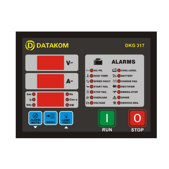
DKG-317 User Manual V-01.19 (01.10.2009) 1. INSTALLATION 1.1 Introduction to the Control Panel The unit is a control and protection panel used in gensets. It shows the measured values on its displays. The unit is designed to provide user friendliness for both the installer and the user. Programming is usually unnecessary, as the factory settings have been carefully selected to fit most applications. -
Page 4: Wiring The Unit
DKG-317 User Manual V-01.19 (01.10.2009) 1.3 Wiring the Unit WARNING: THE UNIT IS NOT FUSED. Use external fuses for Generator phase: U-V-W Battery positive: BAT(+). Install the fuses as nearly as possible to the unit in a place easily accessible for the user. - Page 5 DKG-317 User Manual V-01.19 (01.10.2009) Term Function Technical data Description GROUND O VDC Power supply negative connection. BATTERY POSITIVE +12 or 24VDC The positive terminal of the DC Supply shall be connected to this terminal. The unit operates on both 12V and 24V battery systems.
-
Page 6: Displays
DKG-317 User Manual V-01.19 (01.10.2009) 3. DISPLAYS 3.1 Led Displays The unit has 20 LEDs: -Group_1: Warnings and alarms: This group indicates the existence of abnormal conditions encountered during operation. -Group_2: Unit: This group indicates the unit of the value displayed in the bottom display. -
Page 7: Digital Display
DKG-317 User Manual V-01.19 (01.10.2009) 3.2 Digital Displays The unit has 3 seven segment displays. They show: -Measured parameters, -Service counters, -Statistical counters, -Program parameters. The navigation between different screens in a group is made with the MENU button. Holding the MENU button pressed for 1 second makes the display to switch to the next group. -
Page 8: Alarms And Warnings
DKG-317 User Manual V-01.19 (01.10.2009) 4. ALARMS AND WARNINGS Alarms indicate an abnormal situation in the generating set are divided into 2 priority levels: 1- ALARMS: These are the most important fault conditions and cause: The related alarm led to be on steadily,... -
Page 9: Modes Of Operation
DKG-317 User Manual V-01.19 (01.10.2009) 5. MODES OF OPERATION The genset will run if the front panel RUN button is pressed and will stop if the STOP button is pressed. If requested a starting password may be assigned. The password is set using the program parameter P_048 and has a value between 0 and 999. -
Page 10: Service Request Display
DKG-317 User Manual V-01.19 (01.10.2009) 6.3 Service Request Display This led is designed to help the periodic maintenance of the genset to be made consistently. The periodic maintenance is basically carried out after a given engine hours (for example 200 hours), but even if this amount of engine hours is not fulfilled, it is performed after a given time limit (for example 12 months). -
Page 11: Remote Monitoring And Programming
DKG-317 User Manual V-01.19 (01.10.2009) 6.6 Remote Monitoring and Programming Thanks to its standard serial RS-232 port, the unit offers the remote monitoring and programming feature. remote monitoring programming software downloaded from www.datakom.com.tr internet site. The software allows the visualization and recording of all measured parameters. The recorded parameters may then be analyzed graphically and printed. -
Page 12: Programming
DKG-317 User Manual V-01.19 (01.10.2009) 10. PROGRAMMING The program mode is used to program the timers, operational limits and the configuration of the unit. To enter the program mode, press the MENU button for 5 seconds. The program mode is only allowed if the PROGRAM LOCK input (terminal_23) is left open. - Page 13 DKG-317 User Manual V-01.19 (01.10.2009) Definition Unit Std Val Description If the genset frequency goes under this limit, a SPEED alarm will be generated and the engine Low Freq. Alarm will stop. This alarm will be monitored after delay defined in P_023 when the engine runs.
- Page 14 DKG-317 User Manual V-01.19 (01.10.2009) Definition Unit Std Val Description Temperature sender type This parameter selects the temperature sender type: 0: The sender characteristics are defined in table using parameters P_143 to P_154. 1: VDO 2: DATCON DAH type 3: DATCON DAL type...
- Page 15 DKG-317 User Manual V-01.19 (01.10.2009) Definition Unit Std Val Description Charge input alarm 0: The charge input generates CHARGE warning, and does not stop the engine. 1: The charge input generates CHARGE alarm, and stops the engine. 0: Display genset Line to Neutral voltages, Genset L-L Voltages 1: Display genset Line to Line voltages.
- Page 16 DKG-317 User Manual V-01.19 (01.10.2009) The parameters from P_065 to P_082 define the functions of relay outputs. The unit has 4 relay outputs and 2 of them have programmable functions. The fixed function relays are Fuel and Start. The relays may be extended up to 20 using Relay Extension Modules. RELAY-1 and RELAY-2 with programmable functions are inside the unit.
- Page 17 DKG-317 User Manual V-01.19 (01.10.2009) Parameters from P_083 to P_130 program the functions of the digital inputs. The programmable properties of digital inputs are: -action to be taken upon arrival of the fault signal (alarm, warning,etc...), -when the fault monitoring will be enabled,...
- Page 18 DKG-317 User Manual V-01.19 (01.10.2009) RECTIFIER FAIL INPUT Description Operation 0: Alarm (the engine stops and horn relay operates)) 2: Warning (the horn relay operates) 3: No operation Fault monitoring 0: Always 1: After holdoff timer 2: When mains present...
- Page 19 DKG-317 User Manual V-01.19 (01.10.2009) SPARE-2 FAULT INPUT Description 0: Alarm (the engine stops and horn relay operates)) Operation 2: Warning (the horn relay operates) 3: No operation 0: Always Fault monitoring 1: After holdoff timer 2: When mains present...
- Page 20 DKG-317 User Manual V-01.19 (01.10.2009) Parameters from P_143 to P_154 define the ohm-degrees characteristics of the temperature sender. The sender characteristics will be defined using maximum 6 points. The values should be entered in the increasing order of ohm values. For unused points, ohm values should be entered as 0. An example table is given below.
-
Page 21: Troubleshooting
DKG-317 User Manual V-01.19 (01.10.2009) 11. TROUBLESHOOTING AC voltages or frequency displayed on the unit are not correct: -Check engine body grounding, it is necessary. For testing, connect together the BAT(-) and Neutral terminals together to check if the fault disappears. -
Page 22: Declaration Of Conformity
DKG-317 User Manual V-01.19 (01.10.2009) When the RUN button is pressed, the engine starts to run but the unit gives START FAIL alarm and then the engine stops: -The generator phase voltages are not connected to the unit. Measure the AC voltage between terminals U-V-W and Generator Neutral at the rear of the unit while the engine is running. -
Page 23: Technical Specifications
DKG-317 User Manual V-01.19 (01.10.2009) 13. TECHNICAL SPECIFICATIONS Alternator voltage: 0 to 300 V-AC (Ph-N) Alternator frequency: 0-100 Hz. DC Supply range: 9.0 V-DC to 30.0 V-DC Cranking dropouts: survives 0 V for 100ms Typical current consumption: 100 mA-DC. Maximum current consumption: 350 mA-DC (Relay outputs open) DC relay outputs: 10A / 28 V. -
Page 24: Connection Diagram
DKG-317 User Manual V-01.19 (01.10.2009) 14. CONNECTION DIAGRAM - 24 -...
Need help?
Do you have a question about the DKG-317 and is the answer not in the manual?
Questions and answers