Table of Contents
Advertisement
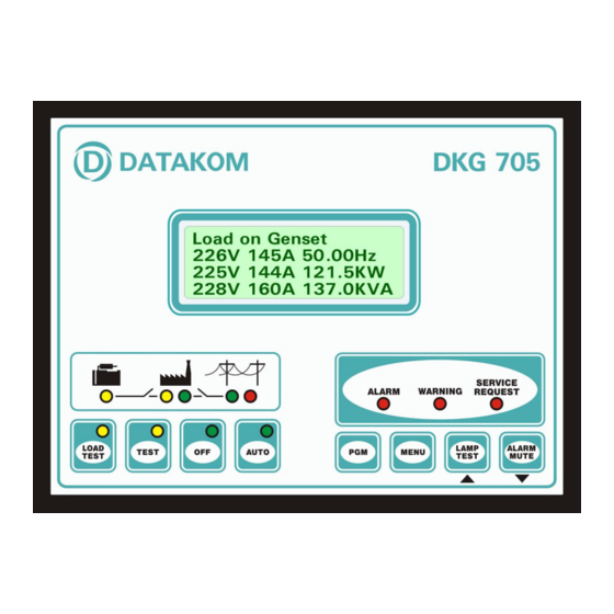
DATAKOM
Electronics Ltd.
DKG-705 AUTOMATIC MAINS FAILURE AND
AND DUAL GENSET PARALLEL FEATURES
Automatic mains failure,
Remote start operation,
Engine control,
Generator protection,
Built in alarms and warnings,
Programmable analogue inputs: 4
Programmable digital inputs: 8
Programmable relay outputs: 7
I/O expansion capability,
LCD display 4 lines by 20 characters,
Periodic maintenance request indicator,
True RMS AC measurements,
Built-in exerciser,
Remote Start capability,
Statistical counters,
datakom@datakom.com.tr
REMOTE START UNIT
WITH PARALLEL TO MAINS
FEATURES
VERSION: 01.16
DKG-705 User's Manual
Tel: +90-216 466 84 60
Fax: +90-216 364 65 65
Event logging,
Field adjustable parameters,
Governor and AVR control outputs,
No break transfer,
Soft transfer,
Paralleling with the mains,
Peak lopping (peak shaving),
Load shedding,
Dual genset parallel with load sharing,
G-59 protections,
Remote monitoring (MS-Windows based),
RS-232 serial port,
Software downloadable from serial port,
Survives cranking dropouts,
Sealed front panel.
DATE: 20-02-2006
Advertisement
Table of Contents

Related Manuals for Datakom DKG-705


Summary of Contents for Datakom DKG-705
- Page 1 DATAKOM DKG-705 User’s Manual datakom@datakom.com.tr Tel: +90-216 466 84 60 Fax: +90-216 364 65 65 Electronics Ltd. DKG-705 AUTOMATIC MAINS FAILURE AND REMOTE START UNIT WITH PARALLEL TO MAINS AND DUAL GENSET PARALLEL FEATURES FEATURES Automatic mains failure, Event logging,...
-
Page 2: Table Of Contents
DATAKOM DKG-705 User’s Manual TABLE OF CONTENTS Section 1. INSTALLATION 1.1. Introduction to the Control Panel 1.2. Mounting the Unit 1.3. Wiring the Unit 2. INPUTS AND OUTPUTS 3. DISPLAYS 3.1. Led Displays 3.2. Digital Display 3.3. Service Request Display 4. -
Page 3: Installation
1. INSTALLATION 1.1 Introduction to the Control Panel The DKG-705 is a control and protection unit used in gensets. The 4 lines by 20 characters LCD display allows the visualization of many measured parameters. The unit is designed to provide user friendliness for both the installer and the user. -
Page 4: Mounting The Unit
Before mounting, remove retaining steel springs from the unit, then pass the unit through the mounting opening. The unit will be maintained in its position by the steel springs. The DKG-705 is factory set for 24V-DC operation. If the unit is used in a 12V-DC system, the 12V jumper terminals must be short-circuited. -
Page 5: Wiring The Unit
DATAKOM DKG-705 User’s Manual 1.3 Wiring the Unit WARNING: THE UNIT IS NOT FUSED. Use external fuses for Mains phases: R-S-T Generator phase: U-V-W Battery positive: BAT(+). Install the fuses as nearly as possible to the unit in a place easily accessible for the user. -
Page 6: Inputs And Outputs
EXTENSION CONNECTOR (OPTIONAL): This connector is intended for the connection of input and output extension modules. The optional relay extension module provides 8 programmable 16A relay outputs. The DKG-705 allows the use of up to 2 I/O extension modules. Term Function... - Page 7 5A-AC terminals to these inputs. Do not connect the same current transformer to other units than CURR_V+ DKG-705 otherwise a unit fault will occur. CURR_V- Connect each terminal of the transformer to CURR_U+ the unit’s related terminal. Do not use CURR_U- common terminals.
- Page 8 5A-AC terminals to these inputs. Do not connect the same current transformer to other units than CURR_S+ DKG-705 otherwise a unit fault will occur. CURR_S- Connect each terminal of the transformer to CURR_T+ the unit’s related terminal. Do not use CURR_T- common terminals.
-
Page 9: Displays
DKG-705 User’s Manual 3. DISPLAY 3.1 Led Displays The DKG-705 has 12 leds, divided in 3 groups: -Group_1: Operating mode: This group indicates the genset function. -Group_2: Mimic diagram: This group indicates the current status of the mains and genset voltages and contactors. -
Page 10: Digital Display
The navigation between different screens in a group is made with the MENU button. Holding the MENU button pressed for 1 second makes the display to switch to the next group. During operation, the DKG-705 will switch automatically between different screens, displaying each time the most important screen for the given situation. - Page 11 DATAKOM DKG-705 User’s Manual Group Screen Description Contents Engine parameters Engine rpm, Battery Voltage Coolant Temperature, Fuel Level Oil Temperature, Oil Pressure Genset power Genset Active Power (KW) , Genset Frequency Genset Apparent Power (KVA), Genset Power Factor (cosΦ Φ Φ Φ )
-
Page 12: Service Request Display
0 and 2500 days with 10 day steps (P_625). If any of the programmed values is zero, this means that the parameter will not be used. For example a maintenance period of 0 days indicates that the DKG-705 will request maintenance only based on engine hours. There will be no time limit. If the engine hours is also selected as 0 hours this will mean that the SERVICE REQUEST display will be inoperative. -
Page 13: Alarms
DATAKOM DKG-705 User’s Manual 4. ALARMS Alarms indicate an abnormal situation in the generating set. The alarms are divided into 3 priority level: 1- SHUTDOWN ALARMS: These are the most important alarm conditions and cause: The genset contactor to be released immediately,... -
Page 14: Shutdown Alarms
DATAKOM DKG-705 User’s Manual 4.1 Shutdown Alarms Definition Source Description Low Oil Pressure Switch Digital Input These shutdown alarms are set depending on the digital input settings. The related program parameters are P_700 to P_776. High Eng.Temp.Switch Digital Input Emergency Stop... -
Page 15: Load Dump Alarms
DATAKOM DKG-705 User’s Manual 4.2 Load Dump Alarms Definition Source Description Low Oil Press.Switch Digital Input These load dump alarms are set depending on the digital input settings. The related program parameters are P_700 to P_776. High Eng.Temp.Switch Digital Input... -
Page 16: Warnings
DATAKOM DKG-705 User’s Manual 4.3 Warnings Definition Source Description Low Oil Press.Switch Digital Input These warnings are set depending on the digital input settings. The related program parameters are P_700 to P_776. High Eng.Temp.Switch Digital Input Emergency Stop Digital Input... - Page 17 DATAKOM DKG-705 User’s Manual Definition Source Description Parallel Mains Fail Internal This general warning is set if any of the protection functions have detected a mains failure during parallel with mains operation. In parallel with mains operation and after the parallel check...
-
Page 18: Modes Of Operation
The modes of operation are selected either by pushing the front panel keys or using the external mode select inputs. External inputs override the front panel selection. If none of the external inputs is active, the unit resumes to the mode selected by the front panel. Following selected mode, the DKG-705 will have different behavior. -
Page 19: Remote Start Operation
DATAKOM DKG-705 User’s Manual 5.2. Remote Start Operation The unit offers the possibility of REMOTE START mode of operation. In this mode the mains phases are not monitored. If the REMOTE START signal is present then the mains will be supposed to fail, inversely if the REMOTE START signal is absent, then mains voltages will be supposed to be present. -
Page 20: Synchronizing With Mains
The frequency and phase matching is made by controlling the engine’s governor module. The DKG-705 compares the mains phase R with the genset phase U. If the engine does not have a speed governor it is not possible to make frequency or phase control. -
Page 21: Avr Control
AVR accept an external adjustment potentiometer. The AVR control will use these inputs, thus the DKG-705 is able to control most of the AVRs found on the market. The impedance range of the AVR output is 300 ohms to 200 K-ohms. The range is adjustable with an internal potentiometer accessible from the back panel of the unit. -
Page 22: Load Transfer Modes
DATAKOM DKG-705 User’s Manual 7. LOAD TRANSFER MODES The DKG-705 has more than one ways of transferring the load from genset to mains and vice versa. These modes are: -transfer with interruption, -no break transfer, (with or without synchronization) -soft transfer. -
Page 23: No Break Transfer
-The mains and generator voltages must have the same phase, -The mains and generator voltages must have the same phase sequence order. The DKG-705 will allow a No Break Transfer only if all of the below conditions are fulfilled: -Mains phase voltages within the programmed limits,... - Page 24 P_A07 Synchronization Fail Timeout: If the phase and voltage synchronization is not successful before the expiration of this timer, then the DKG-705 renounces the No Break Transfer and makes a Transfer with Interruption.
-
Page 25: Soft Transfer
The AVR and GOV control are absolutely necessary to succeed a Soft Transfer. With the basic DKG-705 unit, only a soft transfer from the genset to the mains is possible. The transfer from mains to the genset will simply be a No Break Transfer. -
Page 26: Paralleling With Mains: Peak Lopping
The DKG-705 has a set of programmable parameters to define the Peak Lopping operation. All parameters used in No Break Transfer and Soft transfer are also used in Peak Lopping. Additional parameters are: P_A27 Peak Lopping Enable: This parameter enables/disables the Peak Lopping operation. -
Page 27: Dual Genset Parallel Operation
DKG-705 User’s Manual 9. DUAL GENSET PARALLEL OPERATION The DKG-705 is able to work in Dual Genset Parallel mode without any hardware or software modifications. The only additional accessory needed is a simple RS-232 serial data cable. The units used in paralleling are standard DKG-705s with standard software, which permits very low cost synchronization applications. -
Page 28: Protection Functions For Parallel With Mains
DKG-705 User’s Manual 10. PROTECTION FUNCTIONS FOR PARALLEL WITH MAINS The dkg-705 includes a comprehensive set of protection functions to detect quickly a mains failure during parallel with mains operation. The protections are enabled after the timeout defined by the parameter P_A23 (Parallel Check Timeout) in order not to detect a mains failure during transients caused by the closing of the contactors. - Page 29 It is approximately 1 cycle with a reverse power of 8 times the predefined limit. If mains current transformers are not fitted, the mains reverse power protection will not operate. Thus a full version of DKG-705 is required for this protection. Related parameters:...
-
Page 30: Load Shedding / Dummy Load
DATAKOM DKG-705 User’s Manual 11. LOAD SHEDDING / DUMMY LOAD The load shedding feature consists on the disconnection of the least crucial loads when the genset power approaches to its limits. These loads will be supplied again when the genset power falls below the programmed limit. -
Page 31: Weekly Operation Schedule
DATAKOM DKG-705 User’s Manual 12. WEEKLY OPERATION SCHEDULE In AUTO mode, the unit offers the capability of defining a weekly schedule of operation. The unit has 8 programmable turn-on/turn-off time pairs. These programmable parameters allow the genset to operate automatically only in allowed time limits. -
Page 32: Built-In Exerciser
DATAKOM DKG-705 User’s Manual 13. BUILT-IN EXERCISER The unit offers automatic exerciser operation. The exercise operation may be done on a daily, weekly or monthly basis. The start day and time of the exercise is programmable as well as its duration. The exercise may be done with or without load following programming. -
Page 33: Event Logging
DKG-705 User’s Manual 14. EVENT LOGGING The DKG-705 keeps records of the last 32 events in order to supply information for the service personal. The events are recorded with a time stamp. The date and time information comes from the internal real time clock of the unit. -
Page 34: Statistical Counters
Wipe the unit, if necessary with a soft damp cloth. Do not use chemical agents 17. SOFTWARE DOWNLOAD The DKG-705 application software is held in a flash memory and is field downloadable. The software download is made using the serial port at the back panel of the unit. -
Page 35: Programming
DATAKOM DKG-705 User’s Manual 18. PROGRAMMING The programming mode is used to program the timers, operational limits and the configuration of the unit. The programming mode is protected by a 3 level password system. To enter the program mode, press the PGM button. The program mode will not affect the operation of the unit. - Page 36 DATAKOM DKG-705 User’s Manual Group Definition Level Description Set date and time Unit’s internal date and time used for event logging. Change Password Changes password. Only the password of the current level may be changed. Site ID 20 character ASCII string defining the genset location.
- Page 37 DATAKOM DKG-705 User’s Manual Program Group 4 Group Parameter Definition Max Description 400, 402, Turn_on Weekly schedule turn_on times. The day and 404,406, time information is defined in 15 minute steps. 408, 410, 412, 414 401, 403, Turn-off Weekly schedule turn-off times. The day and 405,407, time information is defined in 15 minute steps.
- Page 38 DATAKOM DKG-705 User’s Manual Group Parameter Definition Unit Min Max Description Gen. Contactor Timer 120 This is the period after the mains contactor has been deactivated and before the generator contactor has been activated. Overcurrent Limit 5000 If the current is over this limit, an...
- Page 39 DATAKOM DKG-705 User’s Manual Mains Freq Low Limit AUTO TEST Mains Freq High Lim AUTO TEST Genset Voltage Fail Timer ! " # $ % & 705_USER.doc - 39 -...
- Page 40 DATAKOM DKG-705 User’s Manual Program Group 6 Group Parameter Definition Unit Min Max Description Reset Maintenance Setting this parameter to 1 will Counters 1) Reset the Time to Service variable to Maintenance Period (days) (P625) value, 2) Reset the Engine Hours to Service variable to Maintenance Period (Engine Hours) (P624) value.
- Page 41 DATAKOM DKG-705 User’s Manual Group Parameter Definition Unit Min Max Description High Bat Voltage 12.0 33.0 If the battery voltage goes over this limit, this will generate a High Battery Voltage Shutdown Alarm and shut down the engine immediately. High Bat Voltage 12.0 33.0 If the battery voltage goes over this limit,...
- Page 42 DATAKOM DKG-705 User’s Manual Group Parameter Definition Unit Min Max Description Engine Heating Type This parameter defines the engine heating method. The genset will not be put under load before engine heating is completed. 0: engine is heated during the period defined by the Engine Heating Timer (P_622).
- Page 43 DATAKOM DKG-705 User’s Manual Group Parameter Definition Unit Max Description Emergency Backup If this parameter is set to 1, in the TEST mode, the load will be transferred to the genset if the mains fail. Frequency Voltage This parameter adjusts the sensitivity for Offset genset frequency reading.
- Page 44 DATAKOM DKG-705 User’s Manual Group Parameter Definition Unit Max Description Exercise start day 168 This parameter defines the start day and and hour hour of the exerciser. Values higher or equal to 168 mean that the exerciser is off. The exercise may be selected to start at the beginning of the any hour of the week.
- Page 45 DKG-705 User’s Manual Program Group: 7 This group defines the properties of the digital inputs and comprises 56 parameters. The DKG-705 unit has 8 programmable digital inputs, each input having 7 parameters. Thus this program group will consist on 8 blocks, each block having the same structure of 7 parameters.
- Page 46 DATAKOM DKG-705 User’s Manual Group Parameter Value Definition Low Oil Pressure Switch High Engine Temperature Switch Emergency Stop Low Coolant Level Alternator High Temperature High Oil Temperature Overload Low Fuel Level Battery Charger Fail Spare Alarm 7 Spare Alarm 6...
- Page 47 DKG-705 User’s Manual Program Group: 8 This group defines the functions of relay outputs. The DKG-705 base unit has 7 relay outputs. The relays may be extended up to 23 using Relay Extension Modules. The function of a given relay output may be selected from a list of 112 entries. Here are the usual functions of the internal relays.
- Page 48 DATAKOM DKG-705 User’s Manual FUNCTION FUNCTION Choke Relay Load Dump: not used Preheat Relay Load Dump: not used Start Relay Load Dump: not used Alarm Relay (timed) Load Dump: not used Generator Contactor Relay Load Dump: not used Mains Contactor Relay...
- Page 49 The analog inputs are capable of measuring resistor values between 0 and 5000 ohms. Thanks to the programmable characteristics, the DKG-705 may be adapted to any brand and type of sensor. Each sensor’s characteristics are defined using a maximum of 8 known points. Each point consists of a pair of value, the first being the resistor value and the second being the corresponding analog measurement.
- Page 50 This is the maximum difference between the Difference mains phase-R and the genset phase-U voltages to enable a NO Break Transfer. Note that the DKG-705 adjusts the AVR output to bring the genset to the same voltage with the mains. 705_USER.doc...
- Page 51 Difference the mains phase-R and the genset phase-U to enable a NO Break Transfer. Note that the DKG-705 adjusts the GOV output to bring the genset to the same phase with the mains. Governor Start 255 This is the rest value of the governor control output.
- Page 52 DATAKOM DKG-705 User’s Manual Timeout energized (for parallel to mains) and before the protections for mains failure are enabled. These protections will deenergize the mains contactor in case of a mains failure in order to prevent the genset from feeding the network.
- Page 53 DATAKOM DKG-705 User’s Manual 0: Single genset loading disabled. On mains Single Genset Load Enable (dual failure both gensets will run and synchronize genset mode) between them, after this the load will be transferred to gensets. 1: Single genset loading enabled. On mains...
- Page 54 DATAKOM DKG-705 User’s Manual Program Group: 11 This group of programs defines the calibration coefficients for the voltage and current measurements. This group is strictly reserved for manufacturing process and must not be modified. Otherwise faulty measurements and unpredicted operation may occur.
-
Page 55: Troubleshooting
DATAKOM DKG-705 User’s Manual 19. TROUBLESHOOTING The genset starts to operate while AC mains are OK or faulty voltage or frequency measurements: Check engine body grounding. AC mains voltages may be outside programmed limits. Mains frequency may be outside limits. - Page 56 DATAKOM DKG-705 User’s Manual The engine does not run after the first start attempt, then the unit does not start again: -The oil pressure switch closes very lately. As the unit senses an oil pressure, it does not start. When oil pressure falls the unit will start.
-
Page 57: Declaration Of Conformity
DATAKOM DKG-705 User’s Manual Synchronization failure: Check the parameters P_A02, P_A04, P_A15 and P_A16. If Dual Genset mode is used then check also P_A39 and P_A40. If one of them is defined too low, this may delay or disable the synchronization process. -
Page 58: Technical Specifications
DATAKOM DKG-705 User’s Manual 21. TECHNICAL SPECIFICATIONS Alternator voltage: 0 to 300 V-AC (Ph-N) Alternator frequency: 0-200 Hz. Mains voltage: 0 to 300 V-AC (Ph-N) Mains frequency: 0-200 Hz. Current Measurement: from current transformers. ../5A. Max load 0.7 VA per phase. -
Page 59: Connection Diagram
DATAKOM DKG-705 User’s Manual 22. CONNECTION DIAGRAM 705_USER.doc - 59 -... - Page 60 DATAKOM DKG-705 User’s Manual DATAKOM Electronics Limited Tel : +90-216-466 84 60 Fax : +90-216-364 65 65 e-mail : datakom@datakom.com.tr http: www.datakom.com.tr 705_USER.doc - 60 -...
Need help?
Do you have a question about the DKG-705 and is the answer not in the manual?
Questions and answers