Table of Contents
Advertisement
Quick Links
DKG-119J User Manual
True RMS measurements
ECU control and monitoring through J1939
CAN
J1939 ECU warnings displayed as text
Various engine brands and models available
Engine control
Generator protection
Built in alarms and warning
Dual genset mutual standby operation
Load shedding, dummy load
Gas engine support
Engine idle speed control
1 phase genset voltage inputs
1 phase genset CT inputs
Engine oil pressure measurement
Engine coolant temperature measurement
Fuel level measurement
Genset active power measurement
Genset power factor measurement
Engine rpm display
Remote Start operation available
Mains simulation input
Engine Idle speed control
Periodic maintenance request
Engine hours counter
Event logging with complete measurement
values
DKG-119J MANUAL AND
REMOTE START UNIT
FEATURES
Stores last 200 events
Statistical counters
3 level password protection
Programmable parameters
All parameters field adjustable
Return to factory settings enabled
Logic level serial port
Firmware downloadable from serial port
Free MS-Windows Remote monitoring SW:
-monitoring and control
- download of parameters
GSM-SMS sending in case of alarm
Modem call in case of alarm
MODBUS communication
128x64 graphic LCD display
Triple language support
Customer logo display capability
Configurable analogue inputs: 3
Configurable digital inputs: 5
Configurable digital outputs: 2
Total digital outputs: 4
Survives cranking dropouts
Sealed front panel
Plug-in connection system for easy
replacement
Dimensions (96x96x53mm)
V-32
(09.07.2012)
CANBUS VERSION
Advertisement
Table of Contents

Subscribe to Our Youtube Channel
Related Manuals for Datakom DKG-119J


Summary of Contents for Datakom DKG-119J
- Page 1 DKG-119J User Manual V-32 (09.07.2012) DKG-119J MANUAL AND REMOTE START UNIT CANBUS VERSION FEATURES True RMS measurements Stores last 200 events ECU control and monitoring through J1939 Statistical counters 3 level password protection J1939 ECU warnings displayed as text Programmable parameters...
-
Page 2: Table Of Contents
DKG-119J User Manual V-32 (09.07.2012) TABLE OF CONTENTS Section 1. INSTALLATION 1.1. Introduction to the Control Panel 1.2. Mounting the Unit 1.3. Wiring the Unit 2. INPUTS AND OUTPUTS 3. DISPLAYS 3.1. Led Displays 3.2. Language Selection 3.3. Digital Display 4. -
Page 3: Installation
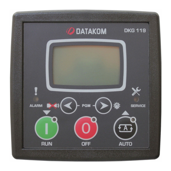
DKG-119J User Manual V-32 (09.07.2012) 1. INSTALLATION 1.1 Introduction to the Control Panel The unit is a control and protection panel used in gensets. It shows the measured values on its displays. The unit is designed to provide user friendliness for both the installer and the user. -
Page 4: Mounting The Unit
DKG-119J User Manual V-32 (09.07.2012) 1.2 Mounting the Unit The unit is designed for panel mounting. The user should not be able to access parts of the unit other than the front panel. Mount the unit on a flat, vertical surface. The unit fits into a standard panel meter opening of 92x92 millimeters. -
Page 5: Inputs And Outputs
DKG-119J User Manual V-32 (09.07.2012) 2. INPUTS AND OUTPUTS RS-232 SERIAL PORT: This connector provides serial data input and output for various purposes like remote monitoring and remote programming. EXTENSION CONNECTOR: This connector is intended for the connection to output extension modules. - Page 6 DKG-119J User Manual V-32 (09.07.2012) Term Function Technical data Description BATTERY POSITIVE +12 or 24VDC The positive terminal of the DC Supply shall be connected to this terminal. The unit operates on both 12V and 24V battery systems. Digital communication...
-
Page 7: Displays
DKG-119J User Manual V-32 (09.07.2012) 3. DISPLAYS 3.1 Led Displays The unit has 5 LEDs, divided in 2 groups: -Group_1: Operating mode: This group indicates the genset function. -Group_2: Warnings and alarms: This group indicates the existence of abnormal conditions encountered during operation. -
Page 8: Digital Display
DKG-119J User Manual V-32 (09.07.2012) 3.3 Digital Display The unit has a graphical 128x64 pixel LCD display. It shows: -Measured parameters, -The company logo, -The alarm list -Software version, -Statistical counters, -Event records, -Program parameters. ◄ ► Navigation between different screens is made with the MENU and MENU buttons. - Page 9 DKG-119J User Manual V-32 (09.07.2012) Screen Description Contents Genset parameters Genset status Engine rpm, Genset Frequency Genset Current L1, Genset Volts L1 Genset power factor, Genset Active Power (KW) Engine parameters Genset status Oil Pressure, Engine rpm Coolant Temperature, Battery Voltage...
-
Page 10: Alarms And Warnings
DKG-119J User Manual V-32 (09.07.2012) 4. ALARMS AND WARNINGS Alarms indicate an abnormal situation in the generating set are divided into 3 priority levels: 1- ALARMS: These are the most important fault conditions and cause: The ALARM led to be on steadily,... - Page 11 DKG-119J User Manual V-32 (09.07.2012) LOW OIL PRESSURE: Set if a signal is detected at the Low Oil Pressure Switch input or the oil pressure value measured from the sender is below the programmed limit. Warning and alarm limits are separately programmable for the oil pressure sender input.
-
Page 12: Modes Of Operation
DKG-119J User Manual V-32 (09.07.2012) 5. MODES OF OPERATION The modes of operation are selected by pushing the front panel keys. Changing the operation mode while the genset is running will result into a behavior suitable for the new operating mode. For example, if the AUTO mode is selected when genset is running at RUN mode, if mains phase voltages are present then the genset will stop. -
Page 13: Sender Type Selection
DKG-119J User Manual V-32 (09.07.2012) 6.2 Sender type Selection The unit has the ability to adapt to any type of oil pressure and temperature senders. The commonly used standard sender characteristics are recorded in memory and selectable from a list. -
Page 14: Engine Idle Speed Operation
DKG-119J User Manual V-32 (09.07.2012) 6.4 Engine Idle Speed Operation It may be required that the engine runs at the idle speed for a programmed duration for engine heating and cooldown. The idle operation duration is adjusted with the parameter Idle Speed Timer. -
Page 15: Mains Simulation (Disable Start)
DKG-119J User Manual V-32 (09.07.2012) 6.7 Mains Simulation (Disable Start) The unit offers an optional SIMULATE MAINS signal input. Any digital input may be assigned as Simulate Mains using Input Function Select program parameters. It is also necessary to set the ACTION program parameter of the related input to 3 in order to prevent any alarms generated from this input. -
Page 16: Delayed Mains Simulation, Battery Charging
DKG-119J User Manual V-32 (09.07.2012) 6.8 Delayed Mains Simulation, Battery Charging The Delayed Mains Simulation feature is used in battery backed up telecom systems where batteries are able to supply the load during a certain period. The genset is requested to run only when battery voltage drops below the critical level. -
Page 17: Dual Genset Mutual Standby Operation
If the priority signal is not applied, then the unit will become the slave one and the other genset will start. Please contact DATAKOM for a complete application manual. - 17 -... -
Page 18: Periodic Service Request Monitoring
DKG-119J User Manual V-32 (09.07.2012) 6.10 Periodic Service Request Monitoring The periodic maintenance is basically carried out after a given engine hours (for example 200 hours), but even if this amount of engine hours is not fulfilled, it is performed after a given time limit (for example 12 months). -
Page 19: Sms Message Sending
GSM SMS message. The new message will indicate all existing alarms, even masked ones. A logic level to RS-232 converter is necessary in order to connect the unit to modem. The necessary GSM modem cable will be supplied by DATAKOM. This is the same cable as PSTN (land) modems. - 19 -... -
Page 20: Remote Monitoring And Programming
FLEXY USB 1.1 TO SERIAL ADAPTER (PRODUCT CODE BF-810) CASECOM USB TO SERIAL CONVERTER (MODEL: RS-01) The necessary PC connection cable will be supplied by DATAKOM. The cable length should not be over 3 meters. 6.15 External Control of the Unit The unit offers total external control through programmable digital inputs. -
Page 21: Resuming To Factory Set Parameters
DKG-119J User Manual V-32 (09.07.2012) 6.16 Resuming to factory set parameters In order to resume to the factory set parameter values: -hold pressed the OFF, LAMP TEST and ALARM MUTE buttons for 5 seconds, -“RETURN TO FACTORY SET” will be displayed -immediately press and hold pressed the ALARM MUTE button for 5 seconds -factory set values will be reprogrammed to the parameter memory. -
Page 22: Fuel Theft / Fuelling Messages
DKG-119J User Manual V-32 (09.07.2012) 6.19 Fuel Theft / Fuelling Messages The unit is able to send SMS messages in fuel theft or fuelling conditions. These SMS messages are sent without creating visible fault condition. These features are enabled by setting the program parameter Engine Parameters > Fuel Consumption / Hour to a value other than 0%. -
Page 23: Changing The Default Engine Speed In Volvo Engines
DKG-119J User Manual V-32 (09.07.2012) 6.21 Changing the Default Engine Speed in Volvo Engines Volvo engines equipped with EMS-II engine control unit have the engine speed selectable through the J1939 – CANBUS. The unit offers the possibility to the user to switch between the primary and secondary speed using the programming menu. - Page 24 DKG-119J User Manual V-32 (09.07.2012) 6.23 Dual Voltage and Frequency The unit offers 2 sets of voltage and frequency protection limit values. The user is allowed to switch between these 2 sets anytime. This feature is especially usefull in dual voltage or frequency gensets for easy switching between 2 operating conditions.
-
Page 25: J1939 Engine Monitoring And Control Port
Engine Type parameter should be set accordingly. The list of available engines is given at the programming section. Please contact DATAKOM for the most current list of engines. If the J1939 port is enabled then the oil pressure, coolant temperature and the engine rpm information are picked up from the ECU unit. - Page 26 DKG-119J User Manual V-32 (09.07.2012) Below is a basic list of fault conditions (x denotes any FMI) DESCRIPTION Fuel filter restriction Fuel pressure sensor fail Low oil level High oil level Oil level sensor fail Low oil pressure Oil pressure sensor fail...
- Page 27 DKG-119J User Manual V-32 (09.07.2012) Below is a basic list of FMI codes. Please be aware that these codes may differ slightly depending on the engine brand and model. DESCRIPTION Value too high” Valid data, but above the normal working range “Value too low”...
-
Page 28: Modbus Communication
Detailed description about the MODBUS protocol is found in the document “Modicon Modbus Protocol Reference Guide”. The web address is: www.modbus.org/docs/PI_MBUS_300.pdf Below is a limited shortlist of readable registers. For the detailed Modbus Application Manual and a complete list of registers please contact DATAKOM. ADDRESS DATA COEFFICIENT... -
Page 29: Event Logging
DKG-119J User Manual V-32 (09.07.2012) 9. EVENT LOGGING The unit keeps record of the last 200 events in order to supply information for the service personal. The genset status information and a comprehensive set of measured values are stored within the event memory. -
Page 30: Maintenance
DKG-119J User Manual V-32 (09.07.2012) 10. STATISTICAL COUNTERS The unit provides a set of non resettable incremental counters for statistical purposes. The counters consist on: -total engine hours -total genset KWh -engine hours to service -time to service -total engine cranks -total genset runs These counters are kept in a non-volatile memory and are not affected from power failures. - Page 31 The unit stores 3 different passwords. Each password allows access to a different level of program parameters. The password level-1 allows access to field adjusted parameters. The level-2 allows access to factory setup. The password level-3 is reserved to Datakom and allows access to calibration parameters. The password level-1 is factory set to „1234‟.
- Page 32 DKG-119J User Manual V-32 (09.07.2012) Program Group: Controller Configuration Parameter Definition, Unit Factory Description (Password Level) This parameter is used to set LCD contrast. Adjust for (1) LCD Contrast the best viewing angle. 0: English language selected. 1: Turkish language selected. This language may...
- Page 33 Simulate Mains signal disappears. (2) Flashing Relay Timer hours Dual Genset Systems: flashing relay toggle timer. Please contact DATAKOM for dual genset mutual stanby operation. This parameter provides the mains and genset voltage limits with a hysteresis feature in order to prevent faulty decisions.
- Page 34 DKG-119J User Manual V-32 (09.07.2012) Program Group: Electrical Parameters Parameter Definition, Unit Factory Description (Password Level) (2) Current Transformer This is the rated value of the current transformer. Ratio The secondary of the transformer will be 5 Amps. If the current goes above this limit, during Overload...
- Page 35 DKG-119J User Manual V-32 (09.07.2012) Program Group: Electrical Parameters Parameter Definition, Unit Factory Description (Password Level) KW 0 If the genset power is negative and goes above this (2) Reverse power warning limit then a REVERSE POWER warning will be limit generated.
- Page 36 DKG-119J User Manual V-32 (09.07.2012) Program Group: Engine Parameters Parameter Definition, Factory Unit Description (Password Level) (2) Low Frequency If the genset frequency goes under this limit, a GENSET LOW SPEED alarm is generated and the engine stops. Shutdown If the genset frequency goes under this limit, a GENSET (1) Low Frequency Warning LOW SPEED warning is generated.
- Page 37 DKG-119J User Manual V-32 (09.07.2012) Program Group: Engine Parameters (continued) Parameter Definition, Unit Factory Description (Password Level) This is the maximum start period. Starting will be (2) Crank Timer automatically cancelled if the genset fires before the timer. This is the waiting period between two start (2) Wait Between Starts attempts.
- Page 38 DKG-119J User Manual V-32 (09.07.2012) Program Group: Engine Parameters (continued) Parameter Definition, Unit Factory Description (Password Level) When the genset frequency reaches this limit, the (3) Crank Cut Frequency 10.0 engine is supposed running and the crank output will release.
- Page 39 DKG-119J User Manual V-32 (09.07.2012) Program Group: Engine Parameters (continued) Parameter Definition, Unit Factory Description (Password Level) 0: The J1939 port is inoperative. 1: The analog measurements (oil, temp, rpm) are (2) J1939 Enable picked_up from the ECU. If the ECU communication is lost, then the engine will be stopped.
- Page 40 DKG-119J User Manual V-32 (09.07.2012) Program Group: Sender Characteristics (password level-2) Parameter Definition Unit Factory Description Oil Pressure Sender point 1, ohm value Oil Pressure Sender Ohms -1 Oil Pressure Sender point 1, bar value Oil Pressure Value -1 Oil Pressure Sender point 2, ohm value...
- Page 41 DKG-119J User Manual V-32 (09.07.2012) Program Group: Input Configuration (Low Oil Pressure Switch) (password level-2) Factory Parameter Definition Unit Description 0: Shutdown (the engine stops immediately) 1: Load Dump (the engine stops after cooldown) Action 2: Warning (the horn relay operates)
- Page 42 DKG-119J User Manual V-32 (09.07.2012) Program Group: Input Configuration (Emergency Stop) (password level-2) Parameter Definition Unit Fac.Set Description 0: Shutdown (the engine stops immediately) 1: Load Dump (the engine stops after cooldown) Action 2: Warning (the horn relay operates) 3: No operation...
- Page 43 DKG-119J User Manual V-32 (09.07.2012) Program Group: Input Configuration (Remote Start Input) (password level-2) Parameter Definition Unit Fac.Set Description 0: Shutdown (the engine stops immediately) 1: Load Dump (the engine stops after cooldown) Action 2: Warning (the horn relay operates)
- Page 44 DKG-119J User Manual V-32 (09.07.2012) The function of a programmable relay output may be selected from the below list. Fuel Oil switch alarm Oil switch warning Alarm Temp switch alarm Temp switch warn. Start Stop Gen. Contactor Emerg.Stop alarm Emerg Stop warn.
- Page 45 DKG-119J User Manual V-32 (09.07.2012) Program Group: Input Function Select (password level-2) Fact. Parameter Definition Description Input 01 Function Select Oil Pressure Switch High Temp. Switch Input 02 Function Select Emergency Stop Input 03 Function Select Spare-1 Input Input 04 Function Select...
- Page 46 DKG-119J User Manual V-32 (09.07.2012) Program Group: Site Id (password level-2) Parameter Definition Factory Set Description This is the site Id string sent at the beginning of an DATAKOM SITE SMS message for the identification of the genset Site Id String sending the SMS message.
- Page 47 DKG-119J User Manual V-32 (09.07.2012) 13. TROUBLESHOOTING AC voltages or frequency displayed on the unit are not correct: -Check engine body grounding, it is necessary. -The error margin of the unit is +/- 3 volts. -If there are faulty measurements only when the engine is running, there may be a faulty charging alternator or voltage regulator on the engine.
- Page 48 DKG-119J User Manual V-32 (09.07.2012) When the REMOTE START signal arrives, the engine starts to run but the unit gives START FAIL alarm and then the engine stops: -The generator phase voltages are not connected to the unit. Measure the AC voltage between terminals GEN L1 and Generator Neutral at the rear of the unit while the engine is running.
- Page 49 DKG-119J User Manual V-32 (09.07.2012) 14. DECLARATION OF CONFORMITY The unit conforms to the EU directives -2006/95/EC (low voltage) -2004/108/EC (electro-magnetic compatibility) Norms of reference: EN 61010 (safety requirements) EN 61326 (EMC requirements) The CE mark indicates that this product complies with the European requirements for safety, health environmental and customer protection.
- Page 50 DKG-119J User Manual V-32 (09.07.2012) 16. CONNECTION DIAGRAM DATAKOM Electronics Ltd. Tel: +90-216-466 84 60 Fax: +90-216-364 65 65 e-mail: datakom@datakom.com.tr http: www.datakom.com.tr - 50 -...
Need help?
Do you have a question about the DKG-119J and is the answer not in the manual?
Questions and answers