Table of Contents
Advertisement
Quick Links
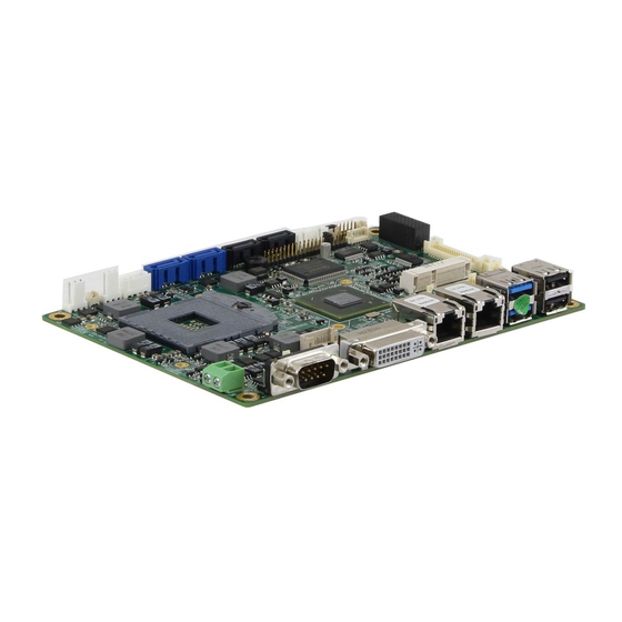
ASB-L8762
EPIC,4" Industrial Motherboard
Socket G2, 3rd and 2nd Generation Intel
Core i3/i5/i7 Processors
User's Manual
Version:1.00
This publication, including all photographs, illustrations and software, is protected under international
copyright laws, with all rights reserved. Neither this manual, nor any of the material contained herein,
may be reproduced without written consent of the author.
All rights are reserved by Aplex Technology Inc.
The information in this document is subject to change
without notice. Please refer to your vendor for the latest information.
Advertisement
Table of Contents

Related Manuals for Aplex ASB-L8762

Summary of Contents for Aplex ASB-L8762
- Page 1 Neither this manual, nor any of the material contained herein, may be reproduced without written consent of the author. All rights are reserved by Aplex Technology Inc. The information in this document is subject to change...
-
Page 2: Table Of Contents
Contents CONTENTS............................2 1 PACKING LIST..........................5 2 DISCLAIMER ..........................5 3 TRADEMARKS ........................... 5 4 SAFETY NOTICES........................5 5 INTRODUCTION ......................... 6 5.1 SPECIFICATIONS....................... 6 5.2 BOARD DIMENSIONS ......................8 5.3 JUMPERS AND CONNECTORS LOCATION..............9 5.4 JUMPERS SETTING AND CONNECTORS ..............11 1. - Page 3 22. COM6 ........................16 23. LAN1,LAN2 ......................17 24. USB45 ........................17 25. USB3 ........................17 26. AUDIO ........................18 27. SIM1 ......................... 18 28. LED1,LED2,LED4..................... 18 29. PCIE_104 ......................... 18 30. M-PCIE1 ........................18 31. H1..........................18 32. BUZ1 ........................18 33.
- Page 4 LED2 ........................23 S1 (PWR BT/LED) ....................23 COM3........................23 COM4........................24 USB10,USB11......................24 APSON1........................24 CF ..........................24 MIO1 ........................25 45. TB-523(OPTION)...................... 26 LED2 ........................26 S1 (PWR BT/LED) ....................26 COM3........................26 JP4........................... 27 COM4........................27 USB10........................28 USB11 ........................
-
Page 5: Packing List
The information in this document is subject to change without further notice. Please refer to your vendor for the latest information. In no event shall Aplex Technology Inc. be liable for hidden defects or damages of any kind, whether consequential or incidental, arising from improper use or installation of the product. -
Page 6: Introduction
4.6 Be sure to unplug the system before installing or removing onboard devices. 5 Introduction ASB-L8762 is a 4” industrial motherboard developed on the basis of Intel HM76,which provides abundant peripheral interfaces to meet the needs of different customers. Also, it features dual GbE ports, 6-COM ports and one Mini PCIE configuration. - Page 7 1 x RS232 header for internal (COM6) pin 9 w/5V/12V/Ring select I/O Card TB-523 (option): 1 x 422/485 select header for internal MIO1 (COM3) 1 x RS232/422/485 select header for internal MIO1 (COM4) Digital I/O 8-bit digital I/O by Pin header by MIO2 4-bit digital Input 4-bit digital Output Support CR2477 Li battery by 2-pin header...
-
Page 8: Board Dimensions
5.2 Board Dimensions (units :mm) - 8 -... -
Page 9: Jumpers And Connectors Location
5.3 Jumpers and Connectors Location Board Top - 9 -... - Page 10 Board Bottom - 10 -...
-
Page 11: Jumpers Setting And Connectors
5.4 Jumpers Setting and Connectors 1. RTC1/SRTC1: (2.0mm Pitch 1X2 Pin Header)CMOS clear jumper, CMOS clear operation will permanently reset old BIOS settings to factory defaults. RTC1/SRTC1 CMOS Open NORMAL (Default) Close 1-2 Clear CMOS Procedures of CMOS clear: a) Turn off the system and unplug the power cord from the power outlet. b) To clear the CMOS settings, use the jumper cap to close pins1 and 2 for about 3 seconds then reinstall the jumper clip back to pins open. -
Page 12: Dc_In2
Pin3 DC+12V Pin4 DC+12V 5. DCIN: (5.08mm Pitch 1x2 Pin Connector),DC12V System power input connector。 Pin# Power Input Pin1 DC+12V Pin2 Ground 6. U1: (Socket G2), installing the 3rd and 2nd GEN intel Core i3/i5/i7CPU Socket. Support for 2nd and 3rd generation Intel® Core™ processors with Turbo Boost Technology 2.0,1 Intel®... -
Page 13: Fp1
module up to 8GB. 12. FP1: (2.0mm Pitch 2x5 Pin Header), Front panel connector. Signal Name Pin# Pin# Signal Name HDD LED+ POWER LED+ Ground Ground Ground RESET+ Ground BUZZER+ BUZZER- Pin1-3: HDD LED, They are used to connect hard disk activity LED. The LED blinks when the hard disk is reading or writing data. -
Page 14: Invt1
Pin4-Pin6(Close) VGA Simulation Disabled Pin4-Pin6(Open) VGA Simulation Enabled use the 2.0mm jumper cap to close pin4 and pin6 14. INVT1: (2.0mm Pitch 1x6 wafer Connector),Backlight control connector for LVDS1. Pin# Signal Name +DC12V +DC12V Ground Ground BKLT_EN BKLT_CTRL Note: Pin6 is backlight control signal, support DC or PWM mode, mode select at BIOS CMOS menu. -
Page 15: Dvi-I
Ground Ground LB_D3_N LA_D3_N LB_D3_P LA_D3_P 16. DVI-I: (DVI-I Connector), Digital Visual Interface-Integrated connector. 17. DP1: (1.25mm Pitch 2x15 Connector,DF13-30P),For Display Port output expansion connector. Signal Name Pin# Pin# Signal Name 5V_S5 5V_S5 DDP_D_HPD PS_ON_ALL- Ground Ground DDP_D_CTL_DAT DDP_D_CTL_CLK DDP_D_AUX+ DDP_D_AUX- DDP_D_D0+ DDP_D_D0-... -
Page 16: Com1
19. COM1: (Type DB9),Rear serial port, standard DB9 Male serial port is provided to make a direct connection to serial devices. Pin# Signal Name DCD# (Data Carrier Detect) RXD (Received Data) TXD (Transmit Data) DTR (Data Terminal Ready) Ground DSR (Data Set Ready) RTS (Request To Send) CTS (Clear To Send) JP1 select Setting... -
Page 17: Lan1,Lan2
Signal Name Pin# Pin# Signal Name Ground JP3 select Setting (RI/5V/12V) 23. LAN1/LAN2 (RJ45 Connector), Rear LAN port, Two standard 10/100/1000M RJ-45 Ethernet ports are provided. Used Intel 82583V chipset, LINK LED (green) and ACTIVE LED (yellow) respectively located at the left-hand and right-hand side of the Ethernet port indicate the activity and transmission state of LAN. -
Page 18: Audio
26. AUDIO: (2.0mm Pitch 2X6 Pin Header), Front Audio, An onboard Realtek ALC662 codec is used to provide high-quality audio I/O ports. Line Out can be connected to a headphone or amplifier. Line In is used for the connection of external audio source via a Line in cable. MIC is the port for microphone input audio. -
Page 19: Pson
RS485 port, three USB ports, one power led, one power button, via a dedicated cable connected to TB-522 MIO1or TB-523 MIO1. Function Signal Name Pin# Pin# Signal Name Function 485+ / 422TX+ 422RX+ COM3 485- / 422TX- 422RX- RS422 COM3 3P3V_S0 Ground WAN_LED... -
Page 20: Sata_P1,Sata_P3
Ground Ground 5V_S5_USB 5V_S5_USB USB9 USB8 USB9_N USB8_N (USB2.0) (USB2.0) USB9_P USB8_P Ground Ground Pin1- Ground: HDD LED, They are used to connect hard disk activity LED. The LED blinks when the hard disk is reading or writing data. Pin2- Pin4: POWER LED, They are used to connect power LED. When the system is powered on or under S0/S1 state, the LED is normally on, when the system is under S4/S5 state, the LED is off. -
Page 21: Sata1,Sata2(Sata3.0)
LPC/ USB2.0/ SMBUS 40. H3: M_SATA1 SCREW HOLES. H3 for mini MSATA card (50.95mmx30mm Socket 52 Pin) assemble. 41. TB-525E11: TB-525E11 connect to ASB-L8762 PCIE_104 connector, PCIE_104 is located at the top,It provides one PCIE X1 slot. - 21 -... -
Page 22: Tb-525E12
TB-525E12 connect to ASB-L8762 PCIE_104 connector, PCIE_104 is located at the top,It provides two PCIE X1 slot. 43. TB-525P1: TB-525P1 connect to ASB-L8762 PCIE_104 connector, PCIE_104 is located at the top,It provides one PCI slot. 44. TB-522(option): ASB-L8762 I/O Card, via a dedicated cable connected to ASB-L8762 MIO1. -
Page 23: Led2
LED2: CF Card LED status. PWR BT: POWER on/off Button, They are used to connect power switch button. The two pins are disconnected under normal condition. You may short them temporarily to realize system startup & shutdown or awaken the system from sleep state. PWR LED: POWER LED status. -
Page 24: Com4
[RS-485] [RS-422] COM4: (Type DB9) Rear serial port, standard DB9 Male serial port is provided to make a direct connection to serial devices. Pin# Signal Name DCD# (Data Carrier Detect) RXD (Received Data) TXD (Transmit Data) DTR (Data Terminal Ready) Ground DSR (Data Set Ready) RTS (Request To Send) -
Page 25: Mio1
MIO1: (DF13-40P) TB-522 MIO1 via a dedicated cable connected to ASB-M801 MIO1. Signal Name Pin# Signal Name 422_RX+ 485+_422TX+ 422_RX- 485-_422TX- Ground 5V_S5 DCD4- RXD4 TXD4 DTR4- Ground DSR4- RTS4- CTS4- RI4- 5V_S5 5V_S5 5V_USB1213 USB3_N USB12_N USB3_P USB12_P Ground Ground Ground Ground... -
Page 26: Tb-523(Option)
45. TB-523(option): ASB-L8762 I/O Card, via a dedicated cable connected to ASB-L8762 MIO1 and MIO2. TB-523 Top: TB-523 Bottom: LED2: CF Card LED status. PWR BT: POWER on/off Button, They are used to connect power switch button. The two pins are disconnected under normal condition. You may short them temporarily to realize system startup &... -
Page 27: Jp4
Ground Ground Note: Use COM3 RS422 or RS485 Function, please enter BIOS CMOS Setup. Path: BIOS Setup Utility \ Advanced /Super IO Configuration \ Serial Port3 Type: [RS-485] [RS-422] JP4: (2.0mm Pitch 2x10 Pin Header) COM4 function setting jumper. Function JP4 Pin# RS232 Close: 3-5,4-6,10-12,11-13 (Default) -
Page 28: Usb10
422_RX- 422_TX- 485- 422_TX+ 485+ Ground Ground USB10: (Single stack USB type A), I/O USB connector, it provides one USB2.0 port, speed up to 480Mb/s. USB11: (2.0mm Pitch 1x4 box Pin Header), I/O USB connector, it provides one USB2.0 port, speed up to 480Mb/s. -
Page 29: Ps_On
Function Pin# Function Ground GPIO_IN1 GPIO_IN2 GPIO_IN3 GPIO_IN4 GPIO_OUT1 GPIO_OUT2 GPIO_OUT3 GPIO_OUT4 (option) PS_ON (2.0mm Pitch 1X2 box Pin Header),ATX Power and Auto Power on jumper setting. PS_ON Mode Close 1-2 Auto Power on (NC) Open 1-2 ATX Power (NC) MIO1: (DF13-40P) TB-523 MIO1 via a dedicated Y cable connected to ASB-L8671 MIO1 and MIO2. - Page 30 GPIO_OUT1 GPIO_OUT2 5V_USB1213 SO_POWER_SENSE USB13_N PWR_LED- USB13_P PS_ON- Ground Ground GPIO_OUT3 GPIO_OUT4 - 30 -...
-
Page 31: Bios Setup Description
6 BIOS Setup Description 6.1 Operations after POST Screen After CMOS discharge or BIOS flashing operation,.Press [Delete] key to enter CMOS Setup. Version 2.15.1227. Copyright (C) 2012 American Megatrends, Inc. BIOS Date:10/16/2013 22:57:49 Ver:L8762V010 Press 〈DEL〉or〈F2〉to enter setup CMOS Checksum fail。Press <DEL> to enter setup。 After optimizing and exiting CMOS Setup, the POST screen displayed for the first time is as follows and includes basic information on BIOS, CPU, memory, and storage devices. -
Page 32: Main Settings
Aptio Setup Utility – Copyright (C) 2012 American Megatrends, Inc. Main Advanced Chipset Boot Security Save & Exit Choose the system System Language Default language System Date [Thu 01/01/2009] System Time [00:00:58] Access Level Administrator BIOS Information Project Version L8771V010 X64 Build Date and Time 10/16/2013 22:57:49 Processor Information... -
Page 33: Advanced Settings
6.4 Advanced Settings Aptio Setup Utility – Copyright (C) 2012 American Megatrends, Inc. Main Advanced Chipset Boot Security Save & Exit PCI,PCI-X and PCI ►PCI Subsystem Settings Express Settings. ►ACPI Settings ►CPU Configuration ►SATA Configuration ►Thermal Configuration ►Intel(R) Rapid Start Technology ►PCH-FW Configuration ►Intel(R) Anti-Theft Technology Configuration ►AMT Configuration... - Page 34 [Enabled] PERR# Generation: [Disabled] [Enabled] SERR# Generation: [Disabled] [Enabled] PCI Express Device Settings: Relaxed Ordering: [Disabled] [Enabled] Extended Tag: [Disabled] [Enabled] No Snoop: [Enabled] [Disabled] Maximum Payload: [Auto] [128 Bytes] [256 Bytes] [512 Bytes] [1024 Bytes] [2048 Bytes] [4096 Bytes] Maximum Read Request: [Auto] [128 Bytes]...
- Page 35 6.4.2 ACPI Settings Enable ACPI Auto Configuration: [Disabled] [Enabled] Enable Hibernation: [Enabled] [Disabled] ACPI Sleep State: [Both S1 and S3 available for OS to choose from] [Suspend Disabled] [S1 only(CPU Stop Clock)] [S3 only(CPU Stop RAM)] Lock Legacy Resources: [Disabled] [Enabled] S3 Video Repost: [Disabled]...
- Page 36 [Enabled] Execute Disable Bit: [Enabled] [Disabled] Intel Virtualization Technology [Enabled] [Disabled] Hardware Prefetcher [Enabled] [Disabled] Adjacent Cache Line Prefetch [Enabled] [Disabled] 6.4.4 SATA Configuration SATA Controller(S): [Enabled] [Disabled] SATA Mode Selection: [IDE] [AHCI] SATA Test Mode: [Disabled] [Enabled] IDE Legacy / Native Mode Selection [Native] [Lrgacy] Serial ATA Port 0...
- Page 37 Software Preserve Unknown Serial ATA Port 5 Empty Software Preserve Unknown 6.4.5 Thermal Configuration Platform Thermal Configuration 6.4.6 Intel(R) Rapid Start Technology Intel(R) Rapid Start Technology [Disabled] 6.4.7 PCH-FW Configuration ME FW Version 8.0.13.1502 ME Firmware Mode Normal Mode ME Firmware Type Full Sku Firmware ME Firmware SKU 1.5MB...
- Page 38 [Enabled] MEBx Debug Message Output [Disabled] [Enabled] Un-Configure ME [Disabled] [Enabled] Amt Wait Timer Disable ME [Disabled] [Enabled] [Enabled] [Disabled] Activate Remote Assistance Process [Disabled] [Enabled] USB Configure [Enabled] [Disabled] PET Progure [Enabled] [Disabled] AMT CIRA Timeout WatchDog [Disabled] [Enabled] OS Timer BIOS Timer 6.4.10 USB Configuration...
- Page 39 [Disabled] [Enabled] Port 60/64 Emulation [Enabled] [Disabled] USB hardware delays and time-outs: USB transfer time-out: [20 sec] [10 sec] [5 sec] [1 sec] Device reset time-out: [20 sec] [10 sec] [30 sec] [40 sec] Device power-up delay [Auto] [Manual] 6.4.11 Super IO Configuration Super IO Configuration Serial Port 1 Configuration Serial Port 2 Configuration...
- Page 40 [Enabled] 6.4.14 Intel(R) Smart Console Technology ISCT Configuration [Disabled] [Enabled] 6.4.15 Serial Port Console Redirection 6.4.16 Intel RC Drivers Version Detail 6.4.17 CPU PPM Configuration CPU PPM Configuration EIST [Enabled] [Disabled] Turbo Mode [Enabled] [Disabled] CPU C3 Report [Enabled] [Disabled] CPU C6 report [Enabled] [Disabled]...
-
Page 41: Chipset Settings
6.5 Chipset Settings Aptio Setup Utility – Copyright (C) 2012 American Megatrends, Inc. Main Advanced Chipset Boot Security Save & Exit System Agent (SA) ►System Agent (SA) Configuration Parameters ►PCH-IO Configuration →←: Select Screen ↑↓ : Select Item Enter: Select +/- : Charge Opt. - Page 42 ►Graphics Configuration IGFX VBIOS Version 2158 IGFX Frequency 650 MHz Primary Display [Auto] [IGFX] [PEG] [PCI] Internal Graphics [Auto] [Disabled] [Enabled] GTT Size [2MB] [1MB] Aperture Size [256MB] [128MB] [512MB] DVMT Pre-allocated [64M] [32M] [96M] [128M] [160M] [192M] [224M] [256M] [288M] [320M] [352M]...
- Page 43 LCD Control: Primary IGFX Boot Display [VBIOS Default] [VGA] [DVI] [LVDS] LCD Panel Type [1280 X 1024 24bit 2ch] [640 X 480 18bit 1ch] [800 X 480 18bit 1ch] [800 X 600 18bit 1ch] [800 X 600 24bit 1ch] [1024 X 768 18bit 1ch] [1024 X 768 24bit 1ch] [1280 X 800 18bit 1ch] [1280 X 1024 18bit 1ch]...
- Page 44 [Level 10 ] [Level 11 ] [Level 12 ] [Level 13] [Level 14 ] [Level 15] Active LFP [Int-LVDS] [No LVDS] [SDVO LVDS] [eDP Port-A] [eDP Port-D] Panel Color Depth [24 Bit] [18 Bit] ►DMI Configuration ►NB PCIe Configuration PEG0 [Not Present] PEG0 –...
- Page 45 Memory RC Version 1.2.2.0 Memory Frequency 1333 Mhz Total Memory 2048 MB (DDR3) DIMM#0 2048 MB (DDR3) DIMM#2 Not Present CAS Latency (tCL) Minimum delay time CAS to RAS (tRPmin) Row Precharge (tRPmin) Active to Precharge (tRPmin) ►GT-Power Management Control GT Info GT2 (0X126) RC6 (Render Standby)
- Page 46 ►PCI Express Root Port 3 ►PCI Express Root Port 4 ►PCI Express Root Port 5 ►PCI Express Root Port 6 ►PCI Express Root Port 7 ►PCI Express Root Port 8 ►USB Configuration XEHCI1 Pre-Boot Driver [Enabled] [Disabled] XEHCI Mode [Smart Auto] HS Port #1 Switchable [Enabled] [Disabled]...
- Page 47 [Disabled] [Enabled] ►BIOS Security Configuration SMI Lock [Disabled] [Enabled] BIOS Lock [Disabled] [Enabled] GPIO Lock [Disabled] [Enabled] BIOS Interface Lock [Enabled] [Disabled] RTC RAM Lock [Enabled] [Disabled] PCH LAN Controller [Disabled] [Enabled] Board Capability [SUS_PWR_DN_ACK] [Deepsx] Display Logic [Enabled] [Disabled] CLKRUN# Logic [Enabled] [Disabled]...
-
Page 48: Boot Settings
[Power off] [Power on] [Last State] 6.6 Boot Settings Aptio Setup Utility – Copyright (C) 2012 American Megatrends, Inc. Main Advanced Chipset Boot Security Save & Exit Boot Configuration Number of seconds to Setup Prompt Timeout Wait for setup Bootup Numlock State [On] Activation key. - Page 49 [Enabled] CSM16 Module Verison 07.69 Gatea20 Active [Upon Request] [Always] Option ROM Messages [Force BIOS] [Keep Current] IN19 Trap Response [Immediate] [Postponed] Boot Option Priorities ► CSM parameters Launch CSM [Enabled] [Disabled] Boot option Filter [UEFI and Legacy] [Legacy only] [UEFI only] Launch PXE OpROM policy [Do not launch]...
-
Page 50: Security Settings
6.7 Security Settings Aptio Setup Utility – Copyright (C) 2012 American Megatrends, Inc. Main Advanced Chipset Boot Security Save & Exit Password Description Set Administrator Password If ONLY the Administrator’s password is set, Then this only limits access to Setup and is Only asked for when entering Setup. -
Page 51: Save & Exit Settings
Security Option of Advanced BIOS Features. If Security Option is set to System, you will be requested to enter the password before system boot and when entering BIOS setup; if Security Option is set to Setup, you will be requested for password for entering BIOS setup. - Page 52 [No] Save Changes Save Setup Values Save configuration? [Yes] [No] Discard Changes Load Previous Values Load Previous Values? [Yes] [No] Restore Defaults Load Optimized Defaults Load optimized Defaults? [Yes] [No] Save user Defaults Save Values as User Defaults Save configuration? [Yes] [No] Restore user Defaults...
Need help?
Do you have a question about the ASB-L8762 and is the answer not in the manual?
Questions and answers