
Related Manuals for LIFAN Power USA Energy Storm Series


Summary of Contents for LIFAN Power USA Energy Storm Series
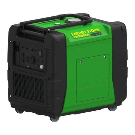
- Page 1 Model ESI-7000iER-EFI Please read this manual carefully before operating your new inverter generator. (CA) in the model number designated California Compliant by CARB 9/1/2016...
- Page 2 OPERATING INSTRUCTIONS AND OWNER’S MANUAL Energy Storm Series ESI-7000iER-EFI PLEASE KEEP AND READ THIS MANUAL CAREFULLY BEFORE OPERATING YOUR NEW ENGINE ID # IS STAMPED LIFAN POWER USA DIGITAL INVERTER ON CRANK CASE GENERATOR RECORD PURCHASE HERE MODEL # ___________________________________...
- Page 3 ATTENTION: Rental Companies and Private Owners who loan this equipment to others! All persons to whom you rent/loan this inverter generator must have access to and read this manual. Keep this owner’s manual with the inverter generator at all times and advise all persons who will operate the machine to read it.
- Page 4 SPECIAL HAZARDS • CO Poisoning: Exhaust from engine contains carbon monoxide, a poisonous gas that can cause carbon monoxide poisoning and possible death if inhaled. • Injection Injury: High-pressure spray can pierce skin and underlying tisses, leading to serious injury and possible amputation. Such an injection injury can result in blood poisoning and/or severe tissue damage.
-
Page 5: Table Of Contents
TABLE OF CONTENTS Preface Operation of Generator ... . . Storing The Unit ....Product Specifications ... Maintenance . -
Page 6: Preface
PREFACE Thank you for choosing LIFAN Power USA for your Power Equipment needs. LIFAN Power USA prides itself on providing quality products at affordable pricing, creating the “Best Equipment Value on Today’s Market!” Your Digital Inverter Generator utilizes our Industrial Grade Gasoline Engines and is intended for OUTDOOR USE ONLY. -
Page 7: Product Specifications
PRODUCT SPECIFICATIONS POWERED... - Page 9 ONLY operate generators outdoors. Exhaust gas must be prevented from entering confined areas. Direct exhaust gas away from windows, doors, ventilation, and other openings. Do not operate this generator inside or under any buildings. WHEN ADDING OR DRAINING FUEL • Turn inverter generator off and let it cool for at least three minutes before removing fuel cap. Loosen cap slowly in order to relieve pressure in the fuel tank.
- Page 10 CAUTION! Improper use and care of this inverter generator will cause damage and shorten its lifespan. Failure to follow these actions will void all warranties. • Use inverter generator only for appropriate and designated purposes. • The dealer or customer helpline (1-866-471-7464) can instruct you on intended uses.
- Page 11 Automotive Type Electronic Fuel Injection System This generator has a computer-controlled fuel and ignition system. An on-board computer, referred to in this manual as an ECU (Engine Control Unit) utilizes a series of virtual maps (lookup tables) that provide values for various aspects of engine performance.
-
Page 12: Controls And Features
CONTROLS AND FEATURES FOLDING HANDLE FUEL CAP CONTROL PANEL LOCKING CASTER WHEELS... - Page 13 CONTROLS AND FEATURES EXHAUST PORT FUEL LEVEL METER FUEL CAP LOCKING CASTER WHEELS CONTROL PANEL ACCESS PANEL LOCKING CASTER WHEELS...
- Page 14 CONTROLS AND FEATURES FOLDING HANDLE ACCESS PANEL (remove for oil fill/drain access, starter access, etc.) LOCKING CASTER WHEELS...
- Page 15 CONTROLS AND FEATURES FOLDING HANDLE ACCESS PANEL (remove for maintenance of air cleaner element, spark plug, valve adjustment, etc.) LOCKING CASTER WHEELS...
- Page 16 CONTROLS AND FEATURES BOX CONTENTS 1 x RV Adapter Plug for • Generator 120 Volt 30amp 1 x 12 Volt Power Cord with Plug • Accessory Kit Service & Alligator Clips 1 x Spark Plug Removal Tool 1 x Owner’s Manual and 1 x NEMA14-30 Male Twist Lock 1 x Oil Drain Tube Warranty Card...
-
Page 17: Pre-Operating Instructions
PRE-OPERATING INSTRUCTIONS: ASSEMBLY 2 PC. SCREWDRIVER BATTERY CHARGER ALLIGATOR CLIPS 12V DC REMOTE START KEY FOBS SPARK PLUG 3-PRONG NEMA MALE TWIST-LOCK PLUG SPARK PLUG WRENCH FUSE OIL DRAIN TUBE EXTENSION Your LIFAN Power USA generator is packaged without fuel and oil. Some assembly is required before operating your LIFAN Power USA Generator. -
Page 18: Setup
PRE-OPERATING INSTRUCTIONS: SETUP CAUTION: Any attempt to start the generator before it has been properly serviced may result in engine failure and void warranty. ADD ENGINE OIL: Refer to the diagrams below. 1. Place generator on level surface. 2. Remove the Right Access Panel (Refer to Controls and Features section). 3. - Page 19 PRE-OPERATING INSTRUCTIONS: SETUP WHEN ADDING FUEL • Turn generator off and let it cool for a minimum of three minutes before removing fuel cap. • Turn and remove cap slowly in order to relieve residual tank pressure. • Always fill the fuel tank with the unit outdoors. •...
- Page 20 PRE-OPERATING INSTRUCTIONS: SETUP CAUTION: Any attempt to start the generator before it has been properly serviced may result in engine failure and void warranty. CHECK AIR CLEANER ELEMENT: Refer to diagram below. 1. Remove the Left Access Cover (Refer to Controls and Features section). 2.
- Page 21 PRE-OPERATING INSTRUCTIONS: SETUP GROUNDING THE GENERATOR: Refer to the diagram below. 1. Connect the Ground Terminal on the generator to an acceptable source of electrical ground, such as a copper-grounding stake, using copper electrical wire with a minimum diameter of 16 gauge.
-
Page 22: Understanding Your Battery
UNDERSTANDING YOUR BATTERY When the key is turned to the ON position the display illuminates, the ECU turns on, the fuel pump turns on long enough to bring up the fuel pressure, and the stepper motor is energized for proper throttle position for starting. Because of the power requirements of these components, the battery in this generator is considered dead at a higher voltage than it would be in other types of equipment. -
Page 23: Battery Assembly & Maintenance
UNDERSTANDING YOUR BATTERY If you are operating the generator through the remote fob and the engine is not run- ning, the remote switch will blink red to remind you to turn the remote switch off. Whenever the remote switch is on, it is drawing current from the battery. When the engine is not running, the battery will not be charged to compensate for the load from the remote receiver, and over time the battery will be drained below the 10.5V necessary to start the generator. -
Page 24: Safety
• To prevent electrical shock from faulty appliances, the generator should be grounded. Connect a length of heavy cable between the generator’s grounding terminal and an external ground source. • This generator is not intended, nor designed, for use as a standby power supply, or to be connected to an automatic transfer switch (ATS);... - Page 25 • Only operate generator outdoors. • Prevent exhaust gas from entering, through windows doors or ventilation intakes, any confined areas. • DO NOT operate generator inside any enclosed or roofed areas. This includes the generator compartment of any recreational vehicle (RV). •...
-
Page 26: Staring Your Generator
ELECTRIC-START MODELS Your ESI 7000iER-EFI is Electric Start Only. 4. Using provided key, turn the ignition switch to the “ON” position. Rotate the key one more position to the “START” position in order to engage the starting motor. Hold key switch in the “START” position until engine starts, for NO MORE than 10 engine rotations. -
Page 27: Operation Of Generator
OPERATION OF GENERATOR GENERATOR OVERLOAD 1. Ensure engine is started and Green power Indicator Light illuminates before plugging in any electrical appliance. 2. Plug in desired 120 Volt load to the 120 Volt U-Ground receptacles. Always plug appliances into the generator with appliance in its “OFF” position. 3. - Page 28 OPERATION OF GENERATOR HOW TO USE YOUR GENERATOR Before connecting or reconnecting an appliance to the generator, check that it is in good order, and that its electrical rating does not exceed that of the generator. This generator has been designed to prevent the engine from NOTE “overspeed”...
- Page 29 OPERATION OF GENERATOR HOW TO USE YOUR GENERATOR • Checking the appliance(s) for proper operation, electrical shorts, and malfunctions. Also ensure the generator has the ability to provide the required starting and running watts of the connected appliance(s). • Ensuring all appliances is in the “OFF” position upon starting the generator. Only start the con- nected appliance(s) when the GREEN Output Indicator Light is illuminated and the generator is providing the necessary power to run the connected appliance(s).
-
Page 30: Storing The Unit
OPERATION OF GENERATOR USAGE IN HIGH ALTITUDE REGIONS: At high altitude, performance will decrease. Engine horsepower will decrease approximately 3.5% for each 1000 feet (305 meters) increase in altitude. At higher altitudes, the density of the atmosphere decreases, so there is less oxygen volume to draw into the cylinder. This means there will be less energy for every power stroke. -
Page 31: Maintenance
MAINTENANCE NOTE: Refer to Following Procedures for Proper Method to Perform Maintenance MAINTENANCE SCHEDULE... - Page 32 MAINTENANCE OIL CHANGE PROCEDURES: Periodic Maintenance of your engine oil should be performed after each 40 hours of use of you Power Equipment Product. Check your engine oil level prior to each use. 1. Start your engine and let it warm up to get the oil warm and thinner. Turn the ignition switch to the “STOP”...
- Page 33 MAINTENANCE AIR CLEANER MAINTENANCE: Refer to Controls and Features section for diagram. 1. Remove Left Access Cover. 2. Remove the Air Cover Case. 3. Pull out the Air Cleaner cartridge following the direction of the arrow. 4. Check the Air Cleaner Element for cleanliness. If needed clean/replace Air Cleaner Element. 5.
- Page 34 MAINTENANCE Spark Plug Wrench Spark Plug Cap SPARK PLUG MAINTENANCE Recommended spark plug: F7RTC To ensure proper engine operation, the spark plug must be properly gapped and free of deposits. 1. Loosen the cover screws and remove the maintenance door. 2.
- Page 35 MAINTENANCE If the generator has been running, the Fuel Filter Fuel Filter muffler will be very hot. Element Removal Element Assembly Allow it to cool before proceeding. Spark Arrestor Maintenance • The spark arrester must be serviced every 100 hours to maintain its efficiency, or a decrease in Horsepower may occur.
-
Page 36: Transporting The Unit
TRANSPORTING THE GENERATOR To prevent fuel spillage when transporting or during temporary storage, the generator should be secured upright in its normal operating position with the ignition switch “OFF” and turn the fuel cap vent to off position. When transporting the generator: •... -
Page 37: Long-Term Storage
LONG-TERM STORAGE OF THE GENERATOR 1. Be sure the storage area is free of excessive humidity and dust, and out of direct sunlight. 2. It is best to keep the tank at least 95% full, as condensation will be less likely to occur in the fuel tank during storage if the tank is full. -
Page 38: Exercising The Generator
EXERCISING THE GENERATOR It is essential that the generator be exercised on a regular basis. This will prevent the accumu- lation of varnish or sludge in the fuel system; remove moisture from the generator windings and help keep the battery properly charged. Additionally, the engine seals and moving components will be lubricated. - Page 39 AC APPLICATION The control panel has three AC breakers: Two (2) 20 A breakers for the 5-20R split duplex recep- tacle, and one (1) 30 A breaker for the L5-30R twist-lock receptacle. The 20A breakers each pro- tect one of the circuits in the 5-20R split duplex receptacle; the left 20A breaker protects the top receptacle, and the right 20A breaker protects the bottom receptacle.
-
Page 40: Powering 12V Dc Devices
POWERING 12V DC DEVICES This generator can be used to power 12V DC devices through the DC receptacle on the control panel while the generator is running. The DC output comes directly from the battery, so power- ing a DC device places a load on the battery. The DC device should require no more than 12V or draw more than 10A (which is the size of the DC breaker). -
Page 41: Jump-Starting The Generator
JUMP-STARTING THE GENERATOR This generator was not designed to be jump-started through the DC receptacle and it is not recommended to do so. If you connect an external battery to the DC receptacle before the generator is started and attempt to start the generator with the key fob or the ignition switch, a jump-start may occur, but it will likely trip the DC breaker. -
Page 42: Digital Display
NO OUTPUT AT THE DC RECEPTACLE DIGITAL DISPLAY This generator is equipped with an LCD digital display that provides continuously-updated status information for the following parameters: • (U) Voltage—Current voltage supplied • (I) Amperage for the generator output • (P) Wattage (power) output for the generator •... -
Page 43: Error & Fault Codes
ERROR - FAULT CODES DIGITAL READ-OUT The low oil alarm system is designed to prevent engine damage caused by an insufficient amount of oil in the crankcase. Before the oil level in the crankcase falls below a safe limit, the low oil alarm system will automatically shut down the engine (the ignition switch will remain in the “ON”... -
Page 44: Wattage Chart
WATTAGE CHART... - Page 45 WATTAGE CHART...
- Page 46 WATTAGE CHART...
- Page 47 CONVERTING AMPS OR HORSEPOWER INTO WATTS If necessary, use these formulas: Watts = Amps x Volts Running Watts* = Horsepower x 932** (for motors) Remember, this worksheet lists average power requirements a particular manufacturer’s device may use more or less than the listed wattage. •...
-
Page 48: Limited Warranty Policy
LIMITED WARRANTY POLICY This warranty is limited to the following Lifan Power and Storm Series products that are distributed by the EquipSource LLC, d/b/a LIFAN POWER USA, located at 2205 Industrial Park Road, Van Buren, AR 72956. Effective date is 4/20/2010. LENGTH OF WARRANTY Residential Use** Commercial/Rental**... - Page 49 LIMITED WARRANTY POLICY This warranty is not valid for products or parts affected or damaged by accident, collision, normal wear, fuel contamination, abuse, neglect, misuse, alteration and/or unsuitable use or unauthorized parts replacement. Mower decks and blades are specifically not warranted for impact or abrasive damage. Warranty becomes void if the customer fails to install, maintain, and/or operate the product in accordance with the instructions and recommended actions of Lifan set forth in the owner’s manual.
- Page 50 LIMITED WARRANTY POLICY DISCLAIMER OF IMPLIED WARRANTIES This limited warranty is in lieu of all other expressed or implied warranties, including any warranty of the unit’s fitness for any particular use and any implied warranty of MERCHANTABILITY otherwise applicable to Lifan Power Equipment and its affiliated companies shall not be liable for any special, incidental or consequential damage, including lost profits.
- Page 51 APPENDIX...
-
Page 52: Appendix: Exploded View / Parts List
EXPLODED VIEW... - Page 57 NOTES...
Need help?
Do you have a question about the Energy Storm Series and is the answer not in the manual?
Questions and answers