
Related Manuals for LIFAN Power USA ESI-2000i


Summary of Contents for LIFAN Power USA ESI-2000i
- Page 1 Model ESI-2000i Please read this manual carefully before operating your new inverter generator. (CA) in the model number designated California Compliant by CARB 8/12/2016...
- Page 2 OPERATING INSTRUCTIONS AND OWNER’S MANUAL Energy Storm Series ESI-2000i PLEASE KEEP AND READ THIS MANUAL CAREFULLY BEFORE OPERATING YOUR NEW LIFAN POWER USA DIGITAL INVERTER GENERATOR RECORD PURCHASE HERE MODEL # ___________________________________ ENGINE ID # _______________________________ DATE OF PURCHASE _______________________...
- Page 3 ATTENTION: Rental Companies and Private Owners who loan this equipment to others! All persons to whom you rent/loan this inverter generator must have access to and read this manual. Keep this owner’s manual with the inverter generator at all times and advise all persons who will operate the machine to read it.
- Page 4 SPECIAL HAZARDS • CO Poisoning: Exhaust from engine contains carbon monoxide, a poisonous gas that can cause carbon monoxide poisoning and possible death if inhaled. • Electric shock: Operating equipment in wet conditions or near water can cause electric shock. •...
-
Page 5: Table Of Contents
TABLE OF CONTENTS Preface Operation of Generator ... . . Product Specifications ... Maintenance ....Safety Instructions . -
Page 6: Preface
PREFACE Thank you for choosing LIFAN Power USA for your Power Equipment needs. LIFAN Power USA prides itself on providing quality products at affordable pricing, creating the “Best Equipment Value on Today’s Market!” Your Digital Inverter Generator utilizes our Industrial Grade Gasoline Engines and is intended for OUTDOOR USE ONLY. -
Page 7: Product Specifications
PRODUCT SPECIFICATIONS POWERED... - Page 9 ONLY operate generators outdoors. Exhaust gas must be prevented from entering confined areas. Direct exhaust gas away from windows, doors, ventilation, and other openings. Do not operate this generator inside or under any buildings. WHEN ADDING OR DRAINING FUEL • Turn generator off and let it cool for at least three minutes before removing fuel cap. Loosen cap slowly in order to relieve pressure in the fuel tank.
- Page 10 CAUTION! Improper use and care of this inverter generator will cause damage and shorten its lifespan. Failure to follow these actions will void all warranties. • Use inverter generator only for appropriate and designated purposes. • The dealer or customer helpline (1-866-471-7464) can instruct you on intended uses.
-
Page 11: Controls And Features
CONTROLS AND FEATURES EZ-CARRY HANDLE FUEL CAP CONTROL PANEL ANTI-VIBRATION LEG PADS... - Page 12 CONTROLS AND FEATURES EXHAUST PORT FUEL CAP ANTI-VIBRATION LEG PADS...
- Page 13 CONTROLS AND FEATURES RECOIL STARTER FUEL CAP EZ-CARRY HANDLE ACCESS PANEL (remove for maintenance of air cleaner element, etc.) ANTI-VIBRATION LEG PADS FUEL SHUTOFF VALVE...
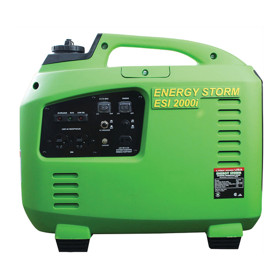
- Page 14 CONTROLS AND FEATURES INDICATOR LIGHTS NEUTRAL DC SOCKET 120V AC RECEPTACLESt GROUND TERMINAL...
-
Page 15: Pre-Operating Instructions
PRE-OPERATING INSTRUCTIONS: ASSEMBLY GENERATOR OIL DRAIN TUBE EXTENSION ALLIGATOR CLIPS SPARK PLUG OIL FILL BOTTLE SPARK PLUG 2 PC. WRENCH SCREWDRIVER UNPACKING THE GENERATOR: 1. Set the Carton on a Flat, Rigid Surface. 2. Remove All Contents from Carton EXCEPT Inverter Generator. 3. -
Page 16: Engine Oil Level Check
PRE-OPERATING INSTRUCTIONS: SETUP CAUTION: Any attempt to start the generator before it has been properly serviced may result in engine failure and void warranty. ADD ENGINE OIL: Refer to the diagrams below. 1. Place generator on level surface. 2. Remove the Access Panel (Refer to Controls and Features section). 3. -
Page 17: Adding Fuel
PRE-OPERATING INSTRUCTIONS: SETUP WHEN ADDING FUEL • Turn generator off and let it cool for a minimum of three minutes before removing fuel cap. • Turn and remove cap slowly in order to relieve residual tank pressure. • Always fill the fuel tank with the unit outdoors. •... -
Page 18: Air Cleaner Element Check
PRE-OPERATING INSTRUCTIONS: SETUP CAUTION: Any attempt to start the generator before it has been properly serviced may result in engine failure and void warranty. CHECK AIR CLEANER ELEMENT: Refer to diagram below. 1. Remove the Left Access Cover (Refer to Controls and Features section). 2. - Page 19 PRE-OPERATING INSTRUCTIONS: SETUP GROUNDING THE GENERATOR: Refer to the diagram below. 1. Connect the Ground Terminal on the generator to an acceptable source of electrical ground, such as a copper-grounding stake, using copper electrical wire with a minimum diameter of 16 gauges.
- Page 20 • To prevent electrical shock from faulty appliances, the generator should be grounded. Connect a length of heavy cable between the generator’s grounding terminal and an external ground source. • This generator is not intended, nor designed, for use as a standby power supply, or to be connected to an automatic transfer switch (ATS);...
- Page 21 • Only operate generator outdoors. • Prevent exhaust gas from entering, through windows doors or ventilation intakes, any confined areas. • DO NOT operate generator inside any enclosed or roofed areas. This includes the generator compartment of any recreational vehicle (RV). •...
-
Page 22: Operation Of Generator
PULL-START (RECOIL) MODELS Your ESI 1000i-CA & ESI 2000i-CA is recoil Start. 3. Place the ignition switch in the “ON” (l) position 4. Grasp starter handle and pull slowly until resistance is felt. Then pull the cord rapidly with a full arm stroke. Allow the rope to return slowly. - Page 23 OPERATION OF GENERATOR GENERATOR OVERLOAD Repeated, substantial overloading that reports an overload condition to the digital display may damage the generator. Marginal overloading that temporarily reports an overload may shorten the service life of the generator. 1. Remove all electrical loads from the generator and investigate CAUTION the cause of the overload.
- Page 24 OPERATION OF GENERATOR LOW OIL ALARM SYSTEM: This model is equipped with a Low Oil Alert System designed to avoid engine damage from insuf- ficient oil in the crankcase. The Low Oil Alarm System will stop the engine automatically before the oil level in the crankcase drops below safe operating levels.
-
Page 25: Maintenance
MAINTENANCE NOTE: Refer to Following Procedures for Proper Method to Perform Maintenance MAINTENANCE SCHEDULE... - Page 26 MAINTENANCE OIL CHANGE PROCEDURES: Periodic Maintenance of your engine oil should be performed after each 40 hours of use of you Power Equipment Product. Check your engine oil level prior to each use. 1. Start your engine and let it warm up to get the oil warm and thinner. Turn the ignition switch to the “STOP”...
- Page 27 MAINTENANCE AIR CLEANER MAINTENANCE: Refer to Controls and Features section for diagram. 1. Remove Left Access Cover. 2. Remove the Air Cover Case. 3. Pull out the Air Cleaner cartridge following the direction of the arrow. 4. Check the Air Cleaner Element for cleanliness. If needed clean/replace Air Cleaner Element. 5.
-
Page 28: Spark Plug Maintenance
MAINTENANCE SPARK PLUG MAINTENANCE Recommended spark plug: F7RTC To ensure proper engine operation, the spark plug must be properly gapped and free of deposits. 1. Loosen the cover screws and remove the maintenance door. 2. Remove the spark plug cap. 3. - Page 29 MAINTENANCE If the generator has been running, the Fuel Filter Fuel Filter muffler will be very hot. Element Removal Element Assembly Allow it to cool before proceeding. Spark Arrestor: • The spark arrester must be serviced every 100 hours to maintain its efficiency, or a decrease in Horsepower may occur.
-
Page 30: Transporting The Unit
TRANSPORTING THE GENERATOR To prevent fuel spillage when transporting or during temporary storage, the generator should be secured upright in its normal operating position with the ignition switch “OFF” and turn the fuel cap vent to off position. When transporting the generator: •... - Page 31 LONG-TERM STORAGE OF THE GENERATOR 1. Be sure the storage area is free of excessive humidity and dust, and out of direct sunlight. 2. It is best to keep the tank at least 95% full, as condensation will be less likely to occur in the fuel tank during storage if the tank is full.
-
Page 32: Troubleshooting
TROUBLESHOOTING IF THE ENGINE WILL NOT START: 1. Check to ensure switches are in the “ON” position. 2. Check engine oil level. Your unit possesses a Low Oil Alarm System that will not allow your engine to start if the oil is below safe operating levels. This feature is installed to increase the life of your engine and prevent engine damage. -
Page 33: Safety
AC APPLICATION 1. 120V AC Receptacles 2. AC Circuit Breaker 3. Grounding Terminal The control panel has an AC breaker (Circuit Protectors): For the 5-20R split duplex receptacle, and one (1) 10a DC breaker for the DC 12v receptacle. Ensure that the breaker is on for the receptacle you want to use. 1. - Page 34 OVERSPEED PROTECTION This generator has been designed to prevent the engine from “overspeed” revving. Overspeed revving occurs when a generator’s on-board monitoring systems detect a drop in voltage from the inverter, and the generator attempts to compensate by revving the engine higher to generate more electricity.
-
Page 35: Low Oil Alarm System
LOW OIL ALARM SYSTEM The low oil alarm system is designed to prevent engine damage caused by an insufficient amount of oil in the crankcase. Before the oil level in the crankcase falls below a safe limit, the low oil alarm system will automatically shut down the engine (the ignition switch will remain in the “ON”... -
Page 36: Wattage Chart
WATTAGE CHART... - Page 37 WATTAGE CHART...
- Page 38 WATTAGE CHART...
- Page 39 CONVERTING AMPS OR HORSEPOWER INTO WATTS If necessary, use these formulas: Watts = Amps x Volts Running Watts* = Horsepower x 932** (for motors) Remember, this worksheet lists average power requirements a particular manufacturer’s device may use more or less than the listed wattage. •...
-
Page 40: Limited Warranty Policy
LIMITED WARRANTY POLICY This warranty is limited to the following Lifan Power and Storm Series products that are distributed by the EquipSource LLC, d/b/a LIFAN POWER USA, located at 2205 Industrial Park Road, Van Buren, AR 72956. Effective date is 4/20/2010. LENGTH OF WARRANTY Residential Use** Commercial/Rental**... - Page 41 LIMITED WARRANTY POLICY This warranty is not valid for products or parts affected or damaged by accident, collision, normal wear, fuel contamination, abuse, neglect, misuse, alteration and/or unsuitable use or unauthorized parts replacement. Mower decks and blades are specifically not warranted for impact or abrasive damage. Warranty becomes void if the customer fails to install, maintain, and/or operate the product in accordance with the instructions and recommended actions of Lifan set forth in the owner’s manual.
- Page 42 LIMITED WARRANTY POLICY DISCLAIMER OF IMPLIED WARRANTIES This limited warranty is in lieu of all other expressed or implied warranties, including any warranty of the unit’s fitness for any particular use and any implied warranty of MERCHANTABILITY otherwise applicable to Lifan Power Equipment and its affiliated companies shall not be liable for any special, incidental or consequential damage, including lost profits.
- Page 43 APPENDIX...
-
Page 44: Appendix: Exploded View / Parts List
EXPLODE... - Page 45 ED VIEW...
- Page 50 ESI-2000i-CA W...
- Page 51 WIRING DIAGRAM...
Need help?
Do you have a question about the ESI-2000i and is the answer not in the manual?
Questions and answers
Don’t seem to have any spark on my Lifan 2000i?
Possible reasons for no spark on a LIFAN Power USA ESI-2000i include:
1. The engine or unit switch is not in the "ON" position.
2. The engine oil level is low, triggering the Low Oil Alarm System that prevents starting.
3. The spark plug is dirty or has an incorrect electrode gap.
4. The spark plug is faulty and may need replacement.
This answer is automatically generated