Table of Contents
Advertisement
Quick Links
Advertisement
Table of Contents

Related Manuals for Prexiso T.O.2


Summary of Contents for Prexiso T.O.2
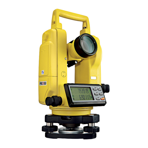
- Page 1 PREXISO T.O.2 User Manual Version 1.0...
- Page 2 T.O.2 | 2 Introduction Purchase Congratulations on the purchase of a T.O.2 instrument. This manual contains important safety directions as well as instructions for setting up the product and operating it. Refer to "7 Safety Directions" for further information. Read carefully through the User Manual before you switch on the product.
- Page 3 Important paragraphs which must be adhered to in practice as they enable the product to be used in a technically correct and efficient manner. Introduction T.O.2 | 3...
-
Page 4: Table Of Contents
Table of Contents T.O.2 | 4 Table of Contents In this manual Chapter Page Description of the System Instrument Case Instrument Components User Interface Function of Buttons Preparation before Measurement Preparation of Battery Erection of the Instrument Leveling up of the Instrument... - Page 5 Index Error of Vertical Circle Care and Transport Transport Storage Cleaning and Drying Safety Directions General Intended Use Limits of Use Responsibilities Hazards of Use Laser Classification 7.6.1 General 7.6.2 Laser Plummet Electromagnetic Compatibility EMC Table of Contents T.O.2 | 5...
-
Page 6: Table Of Contents T.o.2
Table of Contents T.O.2 | 6 Technical Data International Limited Warranty 10 Accessories 11 Error Information... -
Page 7: Description Of The System
All the clamp knobs must be slightly tightened again after the instrument is in place in the case. Description of the System T.O.2 | 7... -
Page 8: Instrument Components
Description of the System T.O.2 | 8 1.2 Instrument Components 1. Screw of handle Instrument compo- nents part 1 of 2 2. Objective lens 3. LCD display I 4. Horizontal drive 5. Levelling screw 6. Handle 7. Laser plummet 8. Tribrach locking lever... - Page 9 1. Focusing knob Instrument compo- nents part 2 of 2 2. Eyepiece 3. Optical sight 4. LCD display II 5. Circular vial 6. Battery case 7. Vertical drive 8. Tubular vial Description of the System T.O.2 | 9...
-
Page 10: User Interface
User Interface T.O.2 | 10 2 User Interface 2.1 Function of Buttons 1. R/L button Description 2. HOLD button 3. V% button 4. 0SET button 5. ON/OFF button 6. Light button Buttons Button Function 1 Other ON/OFF Switch the instru- 1. - Page 11 1. One of the function buttons for entering into initial display of vertical setting of the instrument. angle in angle unit or 2. Button for confirmation after initial setting of the as percentage of instrument. slope User Interface T.O.2 | 11...
-
Page 12: Preparation Before Measurement
Preparation before Measurement T.O.2 | 12 3 Preparation before Measurement 3.1 Preparation of Battery Checking electric Refer to "4.1 Start Up" on how to check the power status of the battery. quantity Before removal of any battery, the instrument must be switched off to avoid malfunction. - Page 13 2. Insert the plug of the charger to the charging port of the Ni-MH battery pack. The green light of the charger turns red, the charging process is started, after 3 to 4 hours when the red light turns green, it indicates that the charging process is finished. Preparation before Measurement T.O.2 | 13...
-
Page 14: Erection Of The Instrument
Preparation before Measurement T.O.2 | 14 3.2 Erection of the Instrument Erection of the 1. Stretch the tripod to a proper hight. instrument 2. Ensure that the measure point is exactly under the central hole of the tripod head. 3. Level up the tripod (this is very important when centering with plumb bob). -
Page 15: Centering
1. Turn the knob of the eyepiece of the optical plummet so that the reticle is in focus; turn the focusing knob so that the ground point a is in focus. Then, loosen the central screw Preparation before Measurement T.O.2 | 15... -
Page 16: Collimation
Preparation before Measurement T.O.2 | 16 to translate the whole instrument (be sure not to turn the instrument) so that the ground point coincides with the central point of the reticle. Retighten the central screw. 2. Perform precise leveling up of the instrument as described in "3.3 Leveling up of the Instrument"... - Page 17 ON/OFF button. 2. Release ON/OFF button when full character display appears and release HOLD + 0SET buttons when four beeps are heard. The instrument enters into initial setting mode and the LCD displays: Preparation before Measurement T.O.2 | 17...
- Page 18 Preparation before Measurement T.O.2 | 18 3. Press button or button for turning over pages and selecting options. 4. Press button for selecting specific content in the options. 5. Finally, press V% button to confirm and enter into angle measuring mode.
- Page 19 • V TILT OFF: Turn off the tilt sensor 6. Inidication of horizontal angle • NO BEEP: Horizontal angle indicator disabled • 90 BEEP: Gives out beep when the instrument is close to 0°, 90°, 180° and 270° Preparation before Measurement T.O.2 | 19...
-
Page 20: Operation Method
Operation Method T.O.2 | 20 4 Operation Method 4.1 Start Up 1. Press and hold ON/OFF button. Start up 2. Release ON/OFF button when full character display appears: 3. Sway the telescope up and down ward when the instrument is at the normal position. The beeper beeps and LCD displays vertical angle. -
Page 21: Measurement Of Angle
(the vertical encoder being on the right). The of the Telescope mechanical errors can be offset by the average of the values of measured in the normal and reverse positions. Normal Reverse Operation Method T.O.2 | 21... - Page 22 Operation Method T.O.2 | 22 Measurement of 1. Measurement of 0° angle of vertical angle vertical angle 0° angle position can be set as follows in the initial setting: 0° 90° 90° 270° 0° 180° 180° 270° ZEN==0 (Zenith 0°) ZEN==90 (Zenith 90°)
- Page 23 When vertical angle is turned into slope, the precision of slope is to the fourth digit after the decimal. The value of the slope is shown in the range of ±99.99% (±45°); outside of this range no value is displayed. Operation Method T.O.2 | 23...
- Page 24 Operation Method T.O.2 | 24 Measurement of 1. Reset of horizontal angle horizontal angle Press 0SET button. The horizontal angle returns to zero. 2. Selecting the direction of measurement of horizontal angle Press R/L button to change the direction of measure- ment of horizontal angle.
-
Page 25: Turning Off The Instrument
4.3 Turning Off the Instrument 1. Press ON/OFF button. Turning off OFF will be displayed at the position of vertical angle display after a beep. 2. Release ON/OFF button. The instrument is turned off. Operation Method T.O.2 | 25... -
Page 26: Measuring Distance Using The Stadia Method
Operation Method T.O.2 | 26 4.4 Measuring Distance Using the Stadia Method Measuring distance 1. Take reading l from the staff gauge using the Stadia hair on the reticle of the tele- using the Stadia scope. method 2. Multiply reading l by 100, we obtain the actual distance L from the target to the meas-... -
Page 27: Installation And Removal Of The Base
3. Turn the knob a clockwise until it reaches the position limit so that the mark points downward. 4. Turn the screw until it can limit position. Operation Method T.O.2 | 27... -
Page 28: Inspection And Adjustment
Inspection and Adjustment T.O.2 | 28 5 Inspection and Adjustment 5.1 Tubular Vial Inspection 1. Fix the instrument to the tripod and roughly level up the instrument and make the tubular vial parallel to the connecting line of two of the three leveling screws on the base. -
Page 29: Circle Vial
1. Set the instument on the tripod (no adjustment is required). 2. Place the cross mark excactly under the instrument. 3. With turned on instrument turn on the laser plummet by pushing the button. 4. Turn the instrument for 180°. Inspection and Adjustment T.O.2 | 29... - Page 30 Inspection and Adjustment T.O.2 | 30 5. If the laser point remains at the center of the cross mark, no adjustment is required; otherwise adjust as follows. 1. Remove the protective cover of the laser Adjustment plummet and adjust the adjustment...
-
Page 31: Perpendicular Of Vertical Hair Of Reticle Of Telescope
2. Aim at object point A in the distance with the normal position of telescope and take the reading of the horizontal angle HRnorm and aim at object A with the reverse posi- tion of the telescope and take the reading of the horizontal angle HRrev then: Inspection and Adjustment T.O.2 | 31... - Page 32 Inspection and Adjustment T.O.2 | 32 Collimation Error C = (HRnorm - HRrev ± 180°)/2 If C <10", no adjustment is required; if C >10", adjustment is required. Adjustment 1. Adjust the horizontal fine motion in the reverse position of the telescope so that the reverse reading HRrev′...
-
Page 33: Index Error Of Vertical Circle
2. Sway the telescope near horizontal plane with instru- ment in the normal position and allow vertical angle to be reset after zero cross. Aim the telescope in the normal position at object P and press 0SET to confirm. Inspection and Adjustment T.O.2 | 33... - Page 34 Inspection and Adjustment T.O.2 | 34 3. Aim the telescope in the reverse position at object P and press 0SET to confirm. With this, the compensa- tion of index error is completed.
-
Page 35: Care And Transport
Always carry the product in its transport container and secure it. Shipping When transporting the product by rail, air or sea, always use the complete original PREXISO packaging, transport container and cardboard box, or its equivalent, to protect against shock and vibration. Shipping, transport... -
Page 36: Storage
Care and Transport T.O.2 | 36 6.2 Storage Product Respect the temperature limits when storing the equipment, particularly in summer if the equipment is inside a vehicle. Refer to "8 Technical Data" for information about tempera- ture limits. Field adjustment After long periods of storage inspect the field adjustment parameters given in this user manual before using the product. -
Page 37: Cleaning And Drying
Dry the product, the transport container, the foam inserts and the accessories at a temper- ature not greater than 40°C /104°F and clean them. Do not repack until everything is completely dry. Always close the transport container when using in the field. Care and Transport T.O.2 | 37... - Page 38 Care and Transport T.O.2 | 38 Cables and plugs Keep plugs clean and dry. Blow away any dirt lodged in the plugs of the connecting cables.
-
Page 39: Safety Directions
Use outside of the intended limits. • Disabling safety systems. • Removal of hazard notices. • Opening the product using tools, for example screwdriver, unless this is specifically permitted for certain functions. • Modification or conversion of the product. Safety Directions T.O.2 | 39... -
Page 40: Limits Of Use
Safety Directions T.O.2 | 40 • Use after misappropriation. • Use of products with obviously recognisable damages or defects. • Use with accessories from other manufacturers without the prior explicit approval of PREXISO. • Aiming directly into the sun. •... -
Page 41: Responsibilities
Manufacturers of The manufacturers of non PREXISO accessories for the product are responsible for non PREXISO acces- developing, implementing and communicating safety concepts for their products, and are... -
Page 42: Hazards Of Use
Safety Directions T.O.2 | 42 • To inform PREXISO immediately if the product and the application becomes unsafe. Warning The person responsible for the product must ensure that it is used in accordance with the instructions. This person is also accountable for the training and the deployment of personnel who use the product and for the safety of the equipment in use. - Page 43 Be careful when pointing the product towards the sun, because the telescope functions as a magnifying glass and can injure your eyes and/or cause damage inside the product. Precautions: Do not point the product directly at the sun. Safety Directions T.O.2 | 43...
- Page 44 Safety Directions T.O.2 | 44 Warning During dynamic applications, for example stakeout procedures there is a danger of acci- dents occurring if the user does not pay attention to the environmental conditions around, for example obstacles, excavations or traffic. Precautions: The person responsible for the product must make all users fully aware of the existing dangers.
- Page 45 Before transportation or shipping contact your local passenger or freight transport company. Warning Using a battery charger not recommended by PREXISO can destroy the batteries. This can cause fire or explosions. Precautions: Only use chargers recommended by PREXISO to charge the batteries.
- Page 46 Safety Directions T.O.2 | 46 Warning Batteries not recommended by PREXISO may be damaged if charged or discharged. They may burn and explode. Precautions: Only charge and discharge batteries recommended by PREXISO.
- Page 47 Product specific treatment and waste management information is available from PREXISO AG. Warning Only PREXISO authorised service workshops are entitled to repair these products. For the charger: Danger The product is not designed for use under wet and severe conditions. If unit becomes wet it may cause you to receive an electric shock.
-
Page 48: Laser Classification
• Touching live components • Using the product after incorrect attempts were made to carry out repairs. Precautions: Do not open the product. Only PREXISO authorised service workshops are entitled to repair these products. 7.6 Laser Classification 7.6.1 General General... -
Page 49: Laser Plummet
IEC 60825-1 (2007-03): "Safety of laser products". • EN 60825-1 (2007-10): "Safety of laser products". Class 2 laser products: These products are safe for momentary exposures but can be hazardous for deliberate staring into the beam. Safety Directions T.O.2 | 49... - Page 50 Safety Directions T.O.2 | 50 Description Value Maximum radiant power 0.95 mW Pulse duration c.w. Pulse repetition frequency c.w. Wavelength 650 nm - 660 nm Warning From a safety perspective class 2 laser products are not inherently safe for the eyes.
- Page 51 PREXISO AG, Glattbrugg Manufactured: 2010 Made in China Laser Radiation Do not stare into the beam Class 2 Laser Product according to IEC 60825-1 (2007 - 03) Po ≤ 1.00 mW λ = 650 - 660 nm Safety Directions T.O.2 | 51...
-
Page 52: Electromagnetic Compatibility Emc
Safety Directions T.O.2 | 52 Exit for laser beam Laser beam 7.7 Electromagnetic Compatibility EMC Description The term Electromagnetic Compatibility is taken to mean the capability of the product to function smoothly in an environment where electromagnetic radiation and electrostatic discharges are present, and without causing electromagnetic disturbances to other equip- ment. - Page 53 Warning Electromagnetic radiation can cause disturbances in other equipment. Although the product meets the strict regulations and standards which are in force in this respect, PREXISO cannot completely exclude the possibility that other equipment may be disturbed. Caution There is a risk that disturbances may be caused in other equipment if the product is used with accessories from other manufacturers, for example field computers, personal computers, two-way radios, non-standard cables or external batteries.
- Page 54 Safety Directions T.O.2 | 54 netic radiation may be exceeded and the correct functioning of other products may be impaired. Precautions: While the product is in use, connecting cables, for example product to external battery, product to computer, must be connected at both ends.
-
Page 55: Technical Data
1", 5" Detection method: H: Dual side V: Single side Precision of angle measurement: 2" Unit of angle: DEG, MIL, GON Display: LCD double side Tilt sensor: Automatic vertical compensation Compensator Range of compensation: ±3' Technical Data T.O.2 | 55... - Page 56 Technical Data T.O.2 | 56 2mm Optical diameter: Laser plummet Maximum radiant power: 0.95 mW Tubular vial: 30" / 2 mm Sensitivity of vial Circular vial: 8' / 2 mm Operating temperature: -20° C to +50° C Environmental spec-...
-
Page 57: International Limited Warranty
This product is subject to the terms and conditions set out in the International Limited Warranty Warranty which you can download from the PREXISO home page at http://www.prexiso.com or collect from your PREXISO distributor. The foregoing warranty is exclusive and is in lieu of all other warranties, terms or condi-... -
Page 58: Accessories
Accessories T.O.2 | 58 10 Accessories List of accessories • 1 set of plumb bob • 1 tool kit (containing a screw driver and 2 needles) • 2 bags of desiccant • 1 rain cover • 1 instruction manual •... -
Page 59: Error Information
Horizontal sensor II error, repair is needed. Vertical sensor error, repair is needed. TILT the tilt sensor out of range, level the insturment again, if invain, repair is needed. Set off the tilt sensor, the instrument can work also. Error Information T.O.2 | 59... - Page 60 PREXISO T.O.2 785191-1.0.0en, Original text © 2010 PREXISO AG, Glattbrugg, Switzerland PREXISO AG www.prexiso.com...
Need help?
Do you have a question about the T.O.2 and is the answer not in the manual?
Questions and answers