
Related Manuals for Prexiso PR400HV


Summary of Contents for Prexiso PR400HV
- Page 1 IMPORTANT: Read before Using PR400HV SELF-LEVELING ROTARY LASER LEVEL LIMITED www.prexiso-eu.com WARRANTY YEARS...
-
Page 2: Important Safety Instructions
IMPORTANT SAFETY INSTRUCTIONS Do not use the product before you have studied the Safety instructions and the User Manual on the enclosed CD or on our Homepage. If you have no such manual, or it is in the wrong language, please ask your agency for an appropriate copy. -
Page 3: Product Overview
PRODUCT OVERVIEW... -
Page 4: Parts Description
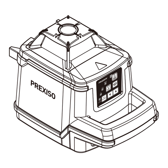
PARTS DESCRIPTION PARTS DESCRIPTION Square point window Spirit level for vertical mode Laser beam outlet Thread 5/8" in vertical mode Keypad Level adjustment screw Handle Thread 5/8" in horizontal mode + plumb point outlet Charger port Battery/rechargeable battery housing KEYPAD AND LED On/Off Cal/Scan Rotation Speed... -
Page 5: Remote Control
REMOTE CONTROL SCAN RL100 CAL. SPEED TILT SLOPE 1. Light indicator 2. Laser dot (0rpm in speed mode) and laser head (in scan mode) moving button (Press this button to clockwise move the laser dot/head). 3. Laser dot (0rpm in speed mode) and laser head (in scan mode) moving button (Press this button to anticlockwise move the laser dot). - Page 6 2. Insert the rechargeable Ni-Hm battery pack directly into the laser. 3. Close and lock the battery cover. WARNING: • Use charging / power adapter only with Ni-Mh battery pack supplied. Charging any other type of battery may result in damage and/or personal harm.
-
Page 7: Operation
SET UP Place the laser on a flat surface or mount it on a tripod. Vertical Position Place the laser upright, with the handle pointing upwards, or mount it on a tripod. NOTE: When the laser is switched on, the laser diode will flash. This indicates that the automatic levelling procedure is under way. -
Page 8: Manual Mode
• Press to switch to scan mode. The scan angle can be adjusted by pressing this key. To move the beam to the right or the left, press AUTOMATIC VERTICAL MODE • Place the laser in its vertical position (handle pointing upwards). Use the level and the foot screw to put the laser in its levelling range if the ground is not even. - Page 9 • It stops the laser beam emission when the laser undergoes a shock or a vibration strong enough to move the laser. The user must then return to the laser to check the settings. DETECTOR FUNCTION The detector is intended for swift finding of pulsating laser beams. PRODUCT OVERVIEW (15) (10)
- Page 10 DISPLAY a. Indicator for detecting accuracy b. Battery indicator c. Audio signal indicator d. Direction indicator “move downward” e. Centre indicator f. Direction indicator ”move upward” OPERATION INSTRUCTIONS 1. Inserting/Replacing the batteries Open Battery compartment and insert two AA batteries in the battery compartment (AA alkaline batteries are recommended for the detecting tool.).
- Page 11 3. Switching On and Off A loud audio signal sounds when switching on the detector and the detector receives the laser beam from the line laser. Therefore, keep the detector away from your ear or other persons when switching on. The loud audio signal can cause hearing defects.
- Page 12 Detector too high: If the laser beam runs through the lower half of the reception area 6, then the direction indicator d on the display. If the audio signal is switched on, a signal sounds at low frequency. Move the detector downward in the arrow direction. Detector in centre position: When the laser beam runs through the reception area 6 at the centre mark 7, the centre indicator e on the display.
- Page 13 (1) Alignment Points-help secure and align rod clamp. (2) Captive Rod Clamp Screw-attaches to the back of detector. (3) Alignment Points-help secure and align rod clamp. (4) Reversible Face-slanted face for round and oval rods; flat face for rectangular and square rods. (5) Clamping Screw Knob-secures clamp to rods by moving the traveling jaw.
- Page 14 outlined below. If these tests show that your laser is no longer calibrated, you must return it to our after-sales service center. • Be sure to allow the laser tool adequate time to Auto-Level (< 60 seconds) prior to a calibration check. •...
-
Page 15: Specifications
-0.5 m 10 m SPECIFICATIONS Horizontal Rotary Accuracy ± 0.75 mm at 10 m Vertical Rotary Accuracy: ± 1.5 mm at 10 m Vertical Up Beam Accuracy: ± 2 mm at 10 m Vertical Down Beam Accuracy: ± 3 mm at 10 m Compensation Range: ±5°... -
Page 16: Maintenance And Care
• Do not use solvent to clean the laser. • Only transport the laser in its original case. Do not leave the Prexiso laser in direct sunlight. Do not expose the laser to high temperatures.The laser body and some internal parts are made of plastic and can warp at high temperatures. -
Page 17: Possible Errors
• off cuts, poor handling, use of unsuitable batteries, poor electrical connections etc. Repairs made other than by our factory, Prexiso service centre or authorized service station relieve Prexiso of further liability under this guarantee. This guarantee is made expressly in place of all other guarantees or warranties, ex- pressed or implied, with respect to quality, merchantability, or fitness for a particular purpose. - Page 18 Dispose of the product appropriately in accordance with the national regulations in force in your country. Adhere to the national and country specific regulations. Ni-Mh Prexiso AG Fabrikstrasse 1, CH-8586 Erlen / Switzerland...
Need help?
Do you have a question about the PR400HV and is the answer not in the manual?
Questions and answers