Table of Contents
Advertisement
Quick Links
Operating instructions
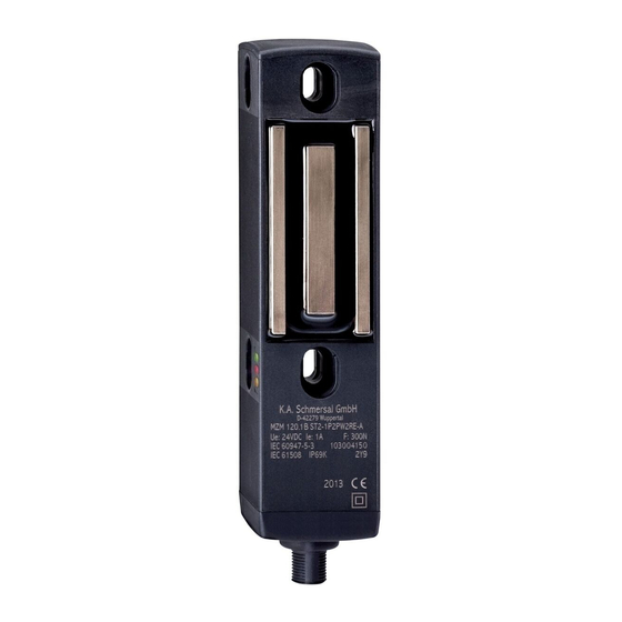
Safety switch with interlocking function
Operating instructions. . . . . . . . . . . .pages 1 to 10
EN
Translation of the original operating instructions
Content
1
About this document
1.1 Function . . . . . . . . . . . . . . . . . . . . . . . . . . . . . . . . . . . . . . . . . . . . . .1
1.2 Target group: authorised qualiied personnel. . . . . . . . . . . . . . . . . .1
1.3 Explanation of the symbols used . . . . . . . . . . . . . . . . . . . . . . . . . . .1
1.4 Appropriate use . . . . . . . . . . . . . . . . . . . . . . . . . . . . . . . . . . . . . . . .1
1.5 General safety instructions . . . . . . . . . . . . . . . . . . . . . . . . . . . . . . .1
1.6 Warning about misuse . . . . . . . . . . . . . . . . . . . . . . . . . . . . . . . . . . .2
1.7 Exclusion of liability . . . . . . . . . . . . . . . . . . . . . . . . . . . . . . . . . . . . .2
2
2.1 Ordering code . . . . . . . . . . . . . . . . . . . . . . . . . . . . . . . . . . . . . . . . .2
2.2 Special versions. . . . . . . . . . . . . . . . . . . . . . . . . . . . . . . . . . . . . . . .2
2.3 Comprehensive quality insurance to 2006/42/EC . . . . . . . . . . . . . .2
2.4 Destination and use . . . . . . . . . . . . . . . . . . . . . . . . . . . . . . . . . . . . .2
2.5 Technical data . . . . . . . . . . . . . . . . . . . . . . . . . . . . . . . . . . . . . . . . .2
2.6 Safety classiication . . . . . . . . . . . . . . . . . . . . . . . . . . . . . . . . . . . . .3
3
3.1 General mounting instructions . . . . . . . . . . . . . . . . . . . . . . . . . . . . .3
3.2 Dimensions . . . . . . . . . . . . . . . . . . . . . . . . . . . . . . . . . . . . . . . . . . .3
4
4.1 General information for electrical connection. . . . . . . . . . . . . . . . . .4
5
5.1 Mode of operation of the safety outputs. . . . . . . . . . . . . . . . . . . . . .4
6
6.1 Diagnostic LED's . . . . . . . . . . . . . . . . . . . . . . . . . . . . . . . . . . . . . . .4
6.2 Safety switch with conventional diagnostic output . . . . . . . . . . . . . .5
6.3 Safety switch with serial diagnostic function . . . . . . . . . . . . . . . . . .6
7
7.1 Functional testing. . . . . . . . . . . . . . . . . . . . . . . . . . . . . . . . . . . . . . .7
7.2 Maintenance . . . . . . . . . . . . . . . . . . . . . . . . . . . . . . . . . . . . . . . . . .7
8
8.1 Disassembly. . . . . . . . . . . . . . . . . . . . . . . . . . . . . . . . . . . . . . . . . . .7
8.2 Disposal . . . . . . . . . . . . . . . . . . . . . . . . . . . . . . . . . . . . . . . . . . . . . .7
9
9.1 Wiring examples . . . . . . . . . . . . . . . . . . . . . . . . . . . . . . . . . . . . . . .7
9.2 Wiring coniguration and connector accessories . . . . . . . . . . . . . . .8
9.3 EC Declaration of conformity . . . . . . . . . . . . . . . . . . . . . . . . . . . . . .9
1. About this document
1.1 Function
This operating instructions manual provides all the information you
need for the mounting, set-up and commissioning to ensure the safe
operation and disassembly of the safety switchgear. The operating
instructions must be available in a legible condition and a complete
version in the vicinity of the device.
1.2 Target group: authorised qualified personnel
All operations described in this operating instructions manual must
be carried out by trained specialist personnel, authorised by the plant
operator only.
Please make sure that you have read and understood these operat-
ing instructions and that you know all applicable legislations regarding
occupational safety and accident prevention prior to installation and
putting the component into operation.
The machine builder must carefully select the harmonised standards
to be complied with as well as other technical specifications for the
selection, mounting and integration of the components.
1.3 Explanation of the symbols used
Information, hint, note:
This symbol is used for identifying useful additional information.
Caution:Failure to comply with this warning notice could
lead to failures or malfunctions.
Warning:Failure to comply with this warning notice could
lead to physical injury and/or damage to the machine.
1.4 Appropriate use
The products described in these operating instructions are developed
to execute safety-related functions as part of an entire plant or machine.
It is the responsibility of the manufacturer of a machine or plant to
ensure the correct functionality of the entire machinery or plant.
The safety switchgear must be exclusively used in accordance with the
versions listed below or for the applications authorised by the manufac-
turer. Detailed information regarding the range of applications can be
found in the chapter "Product description".
1.5 General safety instructions
The user must observe the safety instructions in this operating instruc-
tions manual, labelled with the caution or warning symbol above, the
country-specific installation standards as well as all prevailing safety
regulations and accident prevention rules.
Further technical information can be found in the Schmersal
catalogues or in the online catalogue on the Internet:
www.schmersal.net.
The information contained in this operating instructions manual is
provided without liability and is subject to technical modifications.
The entire concept of the control system, in which the
safety component is integrated, must be validated to
EN ISO 13849-2.
There are no residual risks, provided that the safety instructions as well
as the instructions regarding mounting, commissioning, operation and
maintenance are observed.
EN
MZM 120
1
Advertisement
Table of Contents

Related Manuals for schmersal MZM 120


Summary of Contents for schmersal MZM 120
-
Page 1: Table Of Contents
4.1 General information for electrical connection....4 Further technical information can be found in the Schmersal Operating principles and latching force adjustment catalogues or in the online catalogue on the Internet: 5.1 Mode of operation of the safety outputs. -
Page 2: Warning About Misuse
Relative humidity: 30% ... 95% 2.4 Destination and use - no condensation The MZM 120 is designed for application in safety circuits and is used - non-icing for monitoring the position of movable separating safety guards. A door Protection class: IP67 / IP69K detection sensor monitors the closed condition of the safety guard. -
Page 3: Safety Classiication
Safety switch with interlocking function MZM 120 Electrical data - Safety inputs: At an ambient temperature of ≥ 50 °C, the MZM 120 must be Safety inputs: X1 and X2 (PELV unit) fitted so that it is protected against unintentional contact with Voltage range: −3 V …... -
Page 4: Electrical Connection
4. Electrical connection Description of the MZM 120 latching force adjustment The latching force of the MZM 120 can be set in 8 steps each within 4.1 General information for electrical connection a range of approx. 30 N to approx. 80 N. To this end, the adjustment target MZM 100 TARGET is used directly on the fitted MZM 120. -
Page 5: Safety Switch With Conventional Diagnostic Output
Guard not locked or fault Locking time Table 1: the diagnostic function of the MZM 120 safety switch with additional interlocking function The diagnostic output OUT signals faults before the safety outputs are disabled, thus enabling a controlled shutdown. System condition... -
Page 6: Safety Switch With Serial Diagnostic Function
A fault has occured, which causes the safety outputs to be disabled The necessary integration for the integration of the SD-Gateway is after 30 minutes. The safety outputs initially remain enabled. available for download at www.schmersal.net. Diagnostic error (warning) The response data and the diagnostic data are automatically and... -
Page 7: Set-Up And Maintenance
Operating instructions Safety switch with interlocking function MZM 120 Table 4: Function of the visual diagnostic LED`s, the serial status signals and the safety outputs by means of an example System condition Safety outputs Response byte bit n°: green yellow... -
Page 8: Wiring Coniguration And Connector Accessories
31 components in series Wiring example 2: Series-wiring of the MZM 120 safety switch with serial diagnostic function The safety outputs of the first safety component are wired to the safety-monitoring module. The serial Diagnostic Gateway is connected to the serial diagnostic input of the first safety component. -
Page 9: Ec Declaration Of Conformity
Alboinstr. 56 in Appendix X, 2006/42/EC: 12103 Berlin ID n°: 0035 Place and date of issue: Wuppertal, November 29, 2011 Authorised signature Philip Schmersal Managing Director The currently valid declaration of conformity can be downloaded from the internet at www.schmersal.net. - Page 10 K. A. Schmersal GmbH Industrielle Sicherheitsschaltsysteme Möddinghofe 30, D - 42279 Wuppertal Postfach 24 02 63, D - 42232 Wuppertal Phone: +49 - (0)2 02 - 64 74 - 0 Telefax +49 - (0)2 02 - 64 74 - 1 00 E-Mail: info@schmersal.com...
Need help?
Do you have a question about the MZM 120 and is the answer not in the manual?
Questions and answers