Table of Contents
Advertisement
Quick Links
Advertisement
Table of Contents

Related Manuals for TELEWAVE 44L1


Summary of Contents for TELEWAVE 44L1
- Page 1 Model 44L1/L1P BROADBAND RF WATT METER OPERATION MANUAL ®...
-
Page 2: Table Of Contents
Parts Location Calibration / Adjustment Procedure REFERENCE VSWR Nomograph Jumper Cable Cutting Chart Telewave, Inc. • 660 Giguere Court • San Jose, CA 95133 1-800-331-3396 • 408-929-4400 • www.telewave.com TWDS-8011 Rev. 3/11 • All Contents © 2011 Telewave, Inc. Page 1... -
Page 3: Specifications
Telewave, Inc. Model 44L1/L1P SPECIFICATIONS Table 1-1 lists specifications for the Telewave Model 44L1/L1P 1.01 Broadband RF Wattmeter. These are provided to assist the user in formulating acceptance criteria, determining applications, and for periodic recalibration of the instrument. Minor deviations from these specifications which do not affect performance of the Model 44L1/L1P Wattmeter should not be considered a warranty issue. -
Page 4: General Description
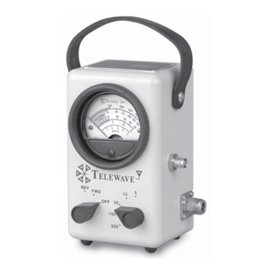
AC power or batteries. A carrying case (Model TC44) is available as an option. The Model 44L1/L1P is ideally suited for mobile, marine, and aircraft applica- tions as well as base stations. Page 3... - Page 5 Telewave, Inc. Model 44L1/L1P Figure 2-1: Model 44L1/L1P Broadband RF Wattmeter Controls and Indicators Page 4...
-
Page 6: Physical Description
Telewave, Inc. Model 44L1/L1P PHYSICAL DESCRIPTION The controls and indicators of the Model 44L1/L1P Broadband RF 3.01 Wattmeter are illustrated in Figure 2-1, and the functions of these elements are described in Table 3-1. Table 3-1 : Model 44L1/L1P Description... - Page 7 Telewave, Inc. Model 44L1/L1P Dual Directional Coupler SOURCE LOAD Figure 3-1: Model 44L1/L1P RF Wattmeter Schematic Table 3-2 : Model 44L1/L1P Parts List DESCRIPTION MFG P/N METER: 20 UA TRIPLETT 7034 KNOB RAYTHEON MS-91528-1P2B SCREW: BUMPER 6-32 TELEWAVE TB44 STRAP: LEATHER...
-
Page 8: Functional Description
Telewave, Inc. Model 44L1/L1P FUNCTIONAL DESCRIPTION The Model 44L1/L1P Wattmeter is made up of two major sections. 4.01 Refer to the schematic diagram in Figure 3-1 for this description. (a) A Dual RF Directional Coupler with directivity of greater than 25 dB. -
Page 9: Accessory List
Telewave, Inc. Model 44L1/L1P Optional Accessories The table below lists the most common accessories for the Model 4.06 44L1/L1P Wattmeter. Consult the current price list or our website for current pricing. Description Part Number TC44 Leather carry case with accessory pouch... -
Page 10: Operation
Telewave, Inc. Model 44L1/L1P OPERATION Unpacking After the Model 44L1/L1P Wattmeter arrives, examine the ship- 5.01 ping container for visible loss or damage. Carefully unpack the wattmeter and examine the exterior for damage. IMPORTANT The Model 44L1/L1P Wattmeter is carefully tested, inspected, and packed before leaving the Telewave factory. -
Page 11: Power Measurements
Step Procedure Set the RF Range Switch to the 500 Watt position. Connect the RF Source to the Model 44L1/L1P FWD input connector, located on the left side of the instrument nearest the mode switch. Connect the RF Load to the Model 44L1/L1P FWD output connector, located on the right side of the instrument nearest the range switch. -
Page 12: Vswr Calculations
Telewave, Inc. Model 44L1/L1P VSWR Calculation The following procedure will assist the user in determining the 5.05 Voltage Standing Wave Ratio. Step Procedure Perform the procedures outlined in 5.03 and 5.04. Record the true incident and reflected power. Refer to the VSWR Chart on the rear of the instrument or Figure 7-1. -
Page 13: Directivity And Insertion Error
VSWR. Since the impedance on either side of 1/2 wavelength is identical, the jumper cable added to the input or output of the Model 44L1/L1P should be of an appro- priate length to equal 1/2 wavelength at the frequency of operation, thus eliminating any error due to the additional length. -
Page 14: Maintenance
Telewave. The following information will be requested in order to assign an RMA: • The Model 44L1/L1P serial number. The ID plate is located on the top of the instrument. Include the date of purchase and Purchase Order number if known. -
Page 15: Parts Location
Telewave, Inc. Model 44L1/L1P Figure 6-1: Adjustment Potentiometers and Parts Location REVERSE RANGES FORWARD RANGES 5 watt range 5 watt range 15 watt range 15 watt range 50 watt range 50 watt range 150 watt range 150 watt range 500 watt range... -
Page 16: Calibration / Adjustment Procedure
6.05 a) The ambient temperature during calibration must be 72.4 degrees. b) The Telewave meter must be calibrated in the intended operating position, either vertical or horizontal. Meters are calibrated by Telewave in the vertical position c) The Telewave wattmeter and any interconnections must use only Type N connectors. - Page 17 Set the wattmeter RF Range Switch to the 5 watt range. Set the RF source to 4 watts output. Adjust R1 until the Telewave wattmeter reads 4 watts. Set the wattmeter RF Range Switch to the 15 watt scale. Set the RF source to produce 11 watts output.
-
Page 18: Reference
Telewave, Inc. Model 44L1/L1P REFERENCE Part 7 contains additional data for the Model 44L1/L1P RF Watt- 7.01 meter which is helpful in making low frequency and VSWR mea- surements. Figure 7-1 (below) shows a nomograph for estimating VSWR 7.02 from the measured incident and reflected power. See 5.05 for cal- culation procedures. - Page 19 Figure 7-2 shows a chart for a jumper cable to be used inline with 7.03 the Model 44L1/L1P Wattmeter to minimize potential measure- ment errors in systems with high VSWR. The chart shows lengths for a 50-ohm, RG-213 jumper cable, including N connectors, using a velocity factor of 0.66 for the cable and connectors.
- Page 20 PRODUCT WARRANTY Products sold by Telewave, Inc. and covered by this Warranty are warranted to be free from defects in material and work man ship at the time of and for a period of one (1) year after delivery to the Buyer. Seller’s entire warranty obligation is limited...
Need help?
Do you have a question about the 44L1 and is the answer not in the manual?
Questions and answers