Table of Contents
Advertisement
Quick Links
44D User Manual
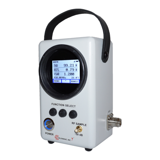
44D Digital/Analog Broadband RF
Wattmeter - User Manual
3 Jul 2018
Firmware Version TiE.01.00
Telewave, Inc.
660 Giguere Court
Phone 408-929-4400
San Jose, CA 95133
Toll Free 800-331-3396
www.telewave.com
sales@telewave.com
support@telewave.com
Copyright © 2018 Telewave, Inc.
Page 1 of 29
Specifications subject to change without notice
3 Jul 2018
Advertisement
Table of Contents

Related Manuals for TELEWAVE 44D


Summary of Contents for TELEWAVE 44D
- Page 1 44D User Manual 44D Digital/Analog Broadband RF Wattmeter - User Manual 3 Jul 2018 Firmware Version TiE.01.00 Telewave, Inc. 660 Giguere Court Phone 408-929-4400 San Jose, CA 95133 Toll Free 800-331-3396 www.telewave.com sales@telewave.com support@telewave.com Copyright © 2018 Telewave, Inc. Page 1 of 29...
-
Page 2: Table Of Contents
APPENDIX: RF SAMPLE PORT ISOLATION ....................22 APPENDIX: SUPPORTED MODULATION TYPES ................... 23 APPENDIX: SPECIAL TEST CASES ........................26 (PTC) R ......................26 OSITIVE RAIN ONTROL ADIOS Copyright © 2018 Telewave, Inc. Page 2 of 29 Specifications subject to change without notice 3 Jul 2018... - Page 3 ........................ 28 AMPLE ATCH ERIFICATION RF S ................... 29 INE TO AMPLE SOLATION ERIFICATION RF S ................... 29 AMPLE ORT TO SOLATION ERIFICATION Copyright © 2018 Telewave, Inc. Page 3 of 29 Specifications subject to change without notice 3 Jul 2018...
-
Page 4: Copyright/Disclaimer/Warranty
Telewave, Inc. Warranty: Products sold by Telewave, Inc. and covered by this Warranty are warranted to be free from defects in material and workmanship at the time of and for a specified period after delivery to the Buyer. -
Page 5: Precautions And Safety Instructions
The inspection includes checking the health of the batteries and creating a battery health report. To return a meter to Telewave; complete the RMA request form located on our web site www.telewave.com, or call 408-929-4400 Option 1 if assistance is needed to compete the RMA. -
Page 6: Quick Start Guide
USB cable, AC power supply, & AC adapter kit) a. Check the box and contents for any damage immediately after it arrives b. In case of any damage or missing item, contact Telewave immediately, 408-929-4400 Opt 1. 2. Charge the Batteries a. -
Page 7: Operation
4-6 hours awake time remain Bars 1 equals >1/4, 2-4 hours awake time remain Flashing equals <1/4, 0-2 hours awake time remain Copyright © 2018 Telewave, Inc. Page 7 of 29 Specifications subject to change without notice 3 Jul 2018... -
Page 8: Power Control
Any live circuits that are monitored with the wattmeter will not be affected if the wattmeter goes to sleep or is turned off while connected to the circuit. Copyright © 2018 Telewave, Inc. Page 8 of 29... -
Page 9: Menu Tree
Configure the meter to High freq (>100 MHz) or Low freq range SETTINGS Adjust meter display parameters INFO & HELP Read only meter attributes and Telewave contact information EXIT Return to the HOME screen For the main MENU and all Sub-Menus ... -
Page 10: Modulation (No Menu)
About Display the hardware and firmware version of the meter Help Display the phone number and email address of Telewave support LAN IP Display the IPv4 Address of the internal WLAN Radio (future use) MAC Add Display the MAC Address of the internal WLAN Radio (future use) ... -
Page 11: Specifications
When the Crest Factor indicates higher than 3 or the PAPR indicates higher than 12 dB, the RMS measurement becomes inaccurate/unusable, and only the Peak reading is reliable. Copyright © 2018 Telewave, Inc. Page 11 of 29 Specifications subject to change without notice... -
Page 12: Usb Connector, Battery And Charging
35% to 85% non-condensing WARNING: The meter is water resistant, but not water proof. If it appears that any liquid has entered the meter (dropped in water), return the meter to Telewave for an internal inspection. Operating Operating Temperature Range (USB Connected) +32°F to +113°F (0°C to +45°C) -
Page 13: Wireless Connectivity (Future)
WLAN (Wireless Local Area Network) 2.4 GHz IEEE 802.11b/g/n internal antenna The WLAN radio is turned off in this firmware. Leave the radio turned off. Copyright © 2018 Telewave, Inc. Page 13 of 29 Specifications subject to change without notice... -
Page 14: Miscellaneous: Accessories, Options, Maintenance
(1 each) 10778 Telewave Part Number Optional Leather Case For transport and storage of the wattmeter and accessories. TC44 Telewave Part Number Optional Connector Adapter Kit The Tele-Dapt 2000™ Adapter Kit is available for easy connection of the wattmeter to cables that do not have the same type of connectors as is fitted on the wattmeter. -
Page 15: Maintenance
There are no user serviceable parts inside the wattmeter. Opening the cover voids the warranty. To return a meter to Telewave; complete the RMA request form located on our web site at www.telewave.com, or call 408-929-4400 Option 1 if assistance is needed to compete the RMA. -
Page 16: Calibration
Carefully follow the instructions for connecting the meter as described below. To return a meter to Telewave; complete the RMA request form located on our web site at www.telewave.com, or call 408-929-4400 Option 1 if assistance is needed to complete the RMA. -
Page 17: Appendix: Connecting The Meter To The Circuit
Meter Connection Diagram Original Circuit ½ WL Increment Insert test cables & 44D at the Component output Primary Cable (1/2 WL increment minus 5”) Secondary Cable (Optional = ½ WL increment) Copyright © 2018 Telewave, Inc. -
Page 18: Calculating The Primary & Secondary Cable Cut Length
Velocity Factor 66% For cables such as: RG-214, RG-213, RG-174, RG-58, and RG-6A Copyright © 2018 Telewave, Inc. Page 18 of 29 Specifications subject to change without notice... - Page 19 28.1 560.0 0.562 0.687 56.2 68.7 22.1 27.0 580.0 0.537 0.662 53.7 66.2 21.2 26.1 600.0 0.515 0.640 51.5 64.0 20.3 25.2 Copyright © 2018 Telewave, Inc. Page 19 of 29 Specifications subject to change without notice 3 Jul 2018...
-
Page 20: Velocity Factor 85
106.8 119.3 42.1 47.0 1.013 1.138 101.3 113.8 39.9 44.8 0.963 1.088 96.3 108.8 37.9 42.8 0.917 1.042 91.7 104.2 36.1 41.0 Copyright © 2018 Telewave, Inc. Page 20 of 29 Specifications subject to change without notice 3 Jul 2018... - Page 21 37.7 42.6 0.928 1.053 92.8 105.3 36.5 41.5 0.900 1.025 90.0 102.5 35.5 40.4 MHz 1000 0.874 0.999 87.4 99.9 34.4 39.3 Copyright © 2018 Telewave, Inc. Page 21 of 29 Specifications subject to change without notice 3 Jul 2018...
-
Page 22: Appendix: Rf Sample Port Isolation
Any live circuits that are monitored with the wattmeter will not be affected if the wattmeter goes to sleep while connected to the circuit. Copyright © 2018 Telewave, Inc. Page 22 of 29 Specifications subject to change without notice... -
Page 23: Appendix: Supported Modulation Types
Analog Amplitude Modulation FDMA Modulation Type Designation Description 6K00A3E, AM (DSB-FC) 3K20A3X Double-Sideband Full-Carrier - Amplitude Modulation SSB-FC 2K80J3E Single-Sideband Full-Carrier - Amplitude Modulation Copyright © 2018 Telewave, Inc. Page 23 of 29 Specifications subject to change without notice 3 Jul 2018... - Page 24 Advanced Civil Speed Enforcement System (ACSES) II 12.5 or 25 KHz GMSK (TDMA) PTC GMSK To measure pwr., radio must be set to transmit on all time slots Copyright © 2018 Telewave, Inc. Page 24 of 29 Specifications subject to change without notice 3 Jul 2018...
- Page 25 Three Slot = 42.500 ms TX & 14.167 ms Off Four Slot = TX continuously (all 56.667 ms Frame) To measure pwr., subscriber must TX on talk group that uses all time slots Copyright © 2018 Telewave, Inc. Page 25 of 29 Specifications subject to change without notice...
-
Page 26: Appendix: Special Test Cases
When a PTC radio is in normal mode, the 44D does not know what or how many time slots have transmit energy; thus only the peak power measurement will be accurate, the average power and calculated values may not be accurate. -
Page 27: Appendix: Specification Validation
PWR-SEN-4GHS Baseline Test Setup This test setup is used to verify the power reading of the 44D. Harmonics on amplifier output suppressed to be below -20 dBc. For all test cases the cables and attenuator between the DUT and the reference meter have been labeled and checked for absolute attenuation across the entire frequency bandwidth of the DUT. -
Page 28: Thru Line Power Measurement Verification
8. Calculate the RF Sample Port VSWR/Return Loss from the difference between the baseline measurement and the delta + calculated loss of the cables and directional coupler Copyright © 2018 Telewave, Inc. Page 28 of 29 Specifications subject to change without notice... -
Page 29: Thru Line To Rf Sample Port Isolation Verification
9. At multiple frequencies check the power measured on the reference power meter 10. Insertion loss @ frequency = ((Generator dBm + Cable Loss dBm) - Reference meter dBm) Copyright © 2018 Telewave, Inc. Page 29 of 29 Specifications subject to change without notice...
Need help?
Do you have a question about the 44D and is the answer not in the manual?
Questions and answers